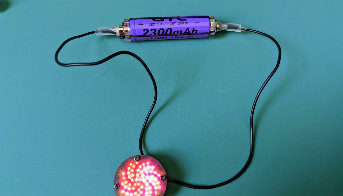

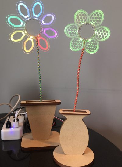
Many of my smaller wearable projects don’t have space for batteries near the electronics, so the power source is often housed in a separate holder. In particular, I’ve found that small LED pendants look quite nice with power/ground wires made out of 26 AWG stranded cord that run behind my neck to the battery holder. This kind of design requires that it be easy to disconnect/reconnect at least one of the the power wires when taking the pendant on/and off, while still providing a secure electrical connection. Small countersunk neodymium magnets are the key to making it work.
There were a few other design considerations as well. I wanted the battery holder to look “wearable” rather than industrial, and it needed to be lightweight and safe. I wanted it to be hard to connect backwards, because “magic smoke” is not funny when you are wearing the electronics at the time!
This simple solution described in this post is easy to make and surprisingly sturdy – allowing different sized cylindrical batteries to be easily swapped in and out. The holder is designed for cylindrical LiPo batteries, because they are well protected against puncture and damage, and don’t require an additional protective case. I tried the same holder design with 10440, 14500 and 16350 batteries and found that it worked well with each.
The video below shows how how it functions:
Components
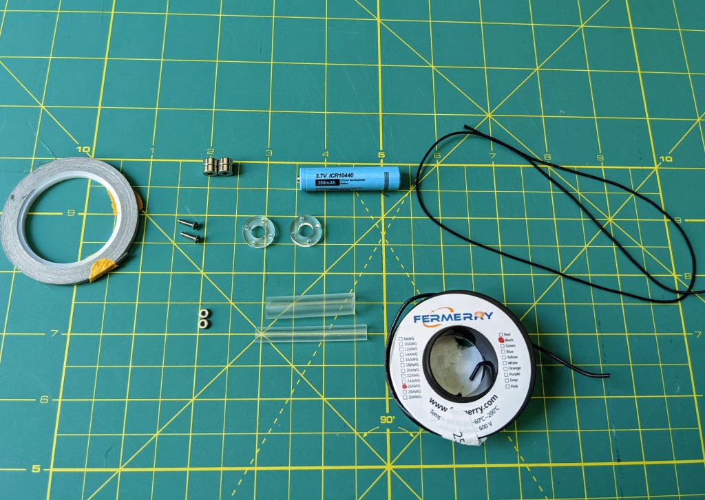
- 1/8″ acrylic or wood for end caps
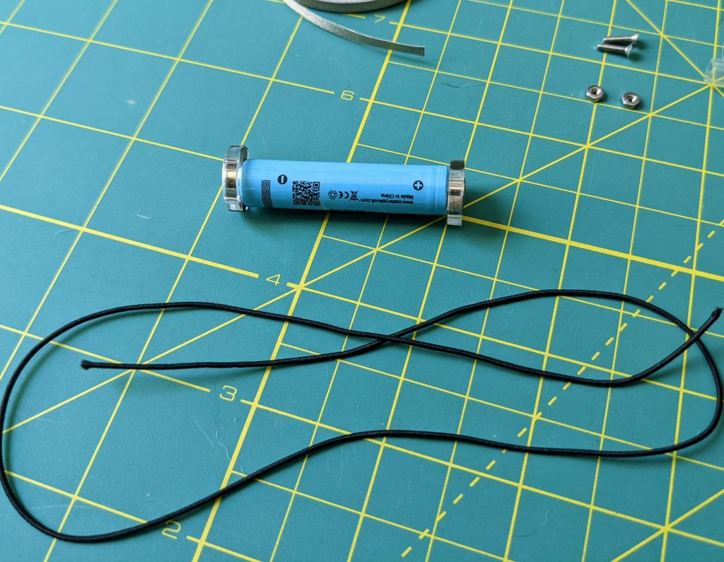
- Thin (I used 1 mm) elastic cord
- Four 1/4″ diameter countersunk neodynium magnets – two of each polarity (the ones listed here come in complenentary pairs and have holes that take a #2 flat-head screw)
- Two M2 flat head screws (I used 8 mm long ones, but any length from 6-12 mm should work)
- Two M2 nuts
- Conductive tape (this cloth tape from Brown Dog Gadgets is sturdier than copper tape)
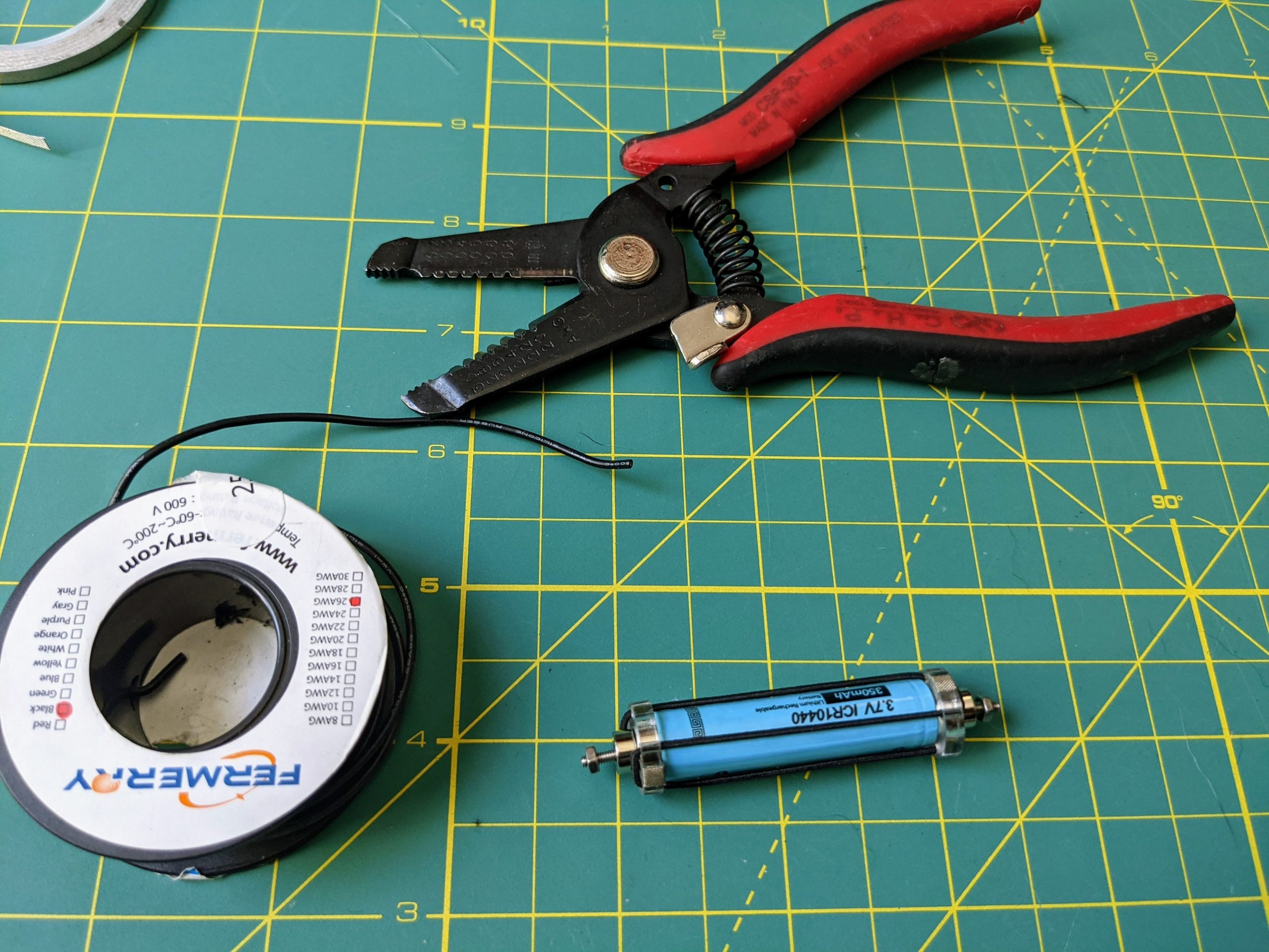
- 26 AWG stranded wire (I use black wire for the aesthetics)
- Shrink tube (1/2″ diameter for magnets + about 3/8″ diameter for the stranded wire)
- Small cylindrical LiPo battery (e.g. 10440, 14500, 16350 etc…)
Tools
- Wire stripper
- Small screwdriver
- Laser cutter to cut the acrylic (a drill press with cutting wheel might work)
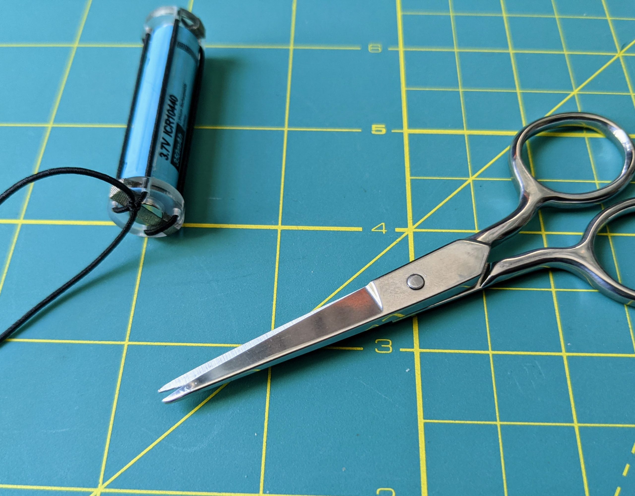
- Scissors
Assembly
Step 1: Laser cut disks
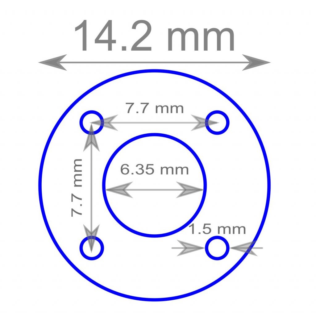
Laser cut two small circles of acrylic with holes that are just large enough to hold the magnets, and which also contain four 1.5 mm holes for stringing the elastic cord. The layout I used for my disks is shown here, though the only critical measurement is the size of the center hole, which must match the magnet size. The rest of the dimensions can differ a bit.
Step 2: Tape magnets into disks
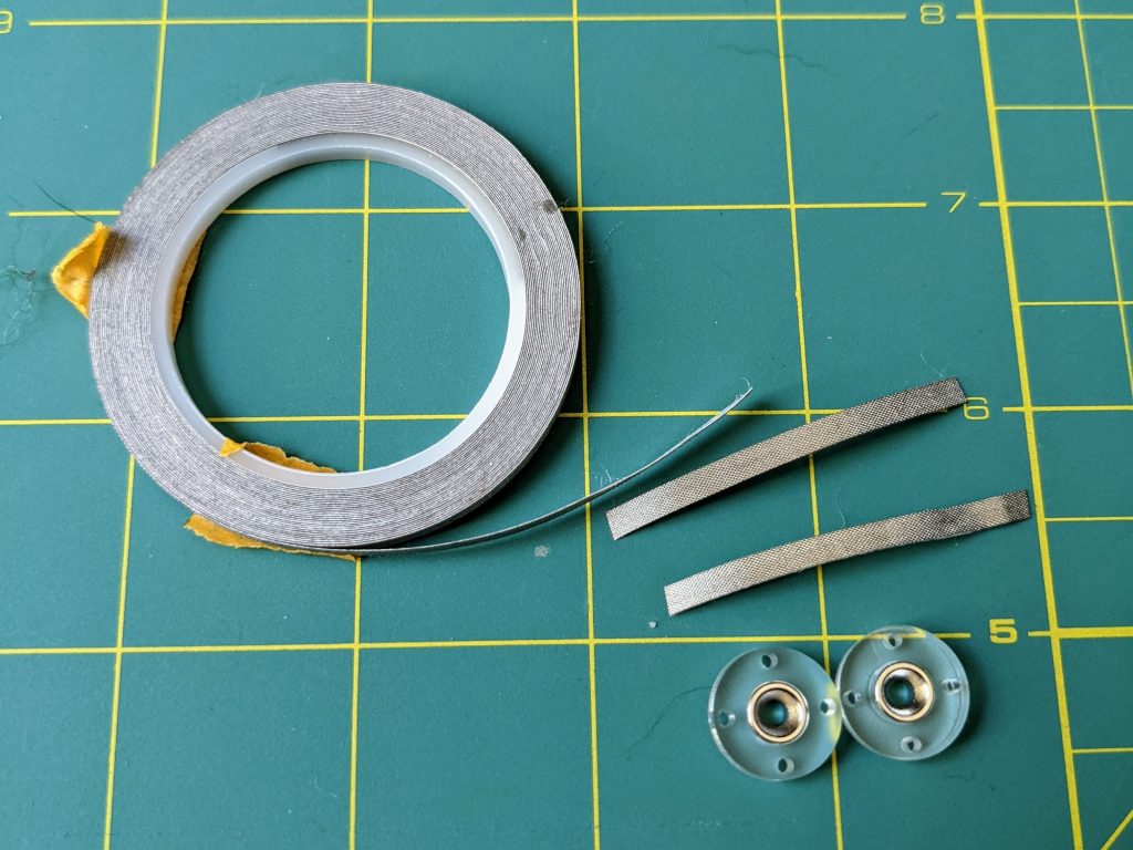
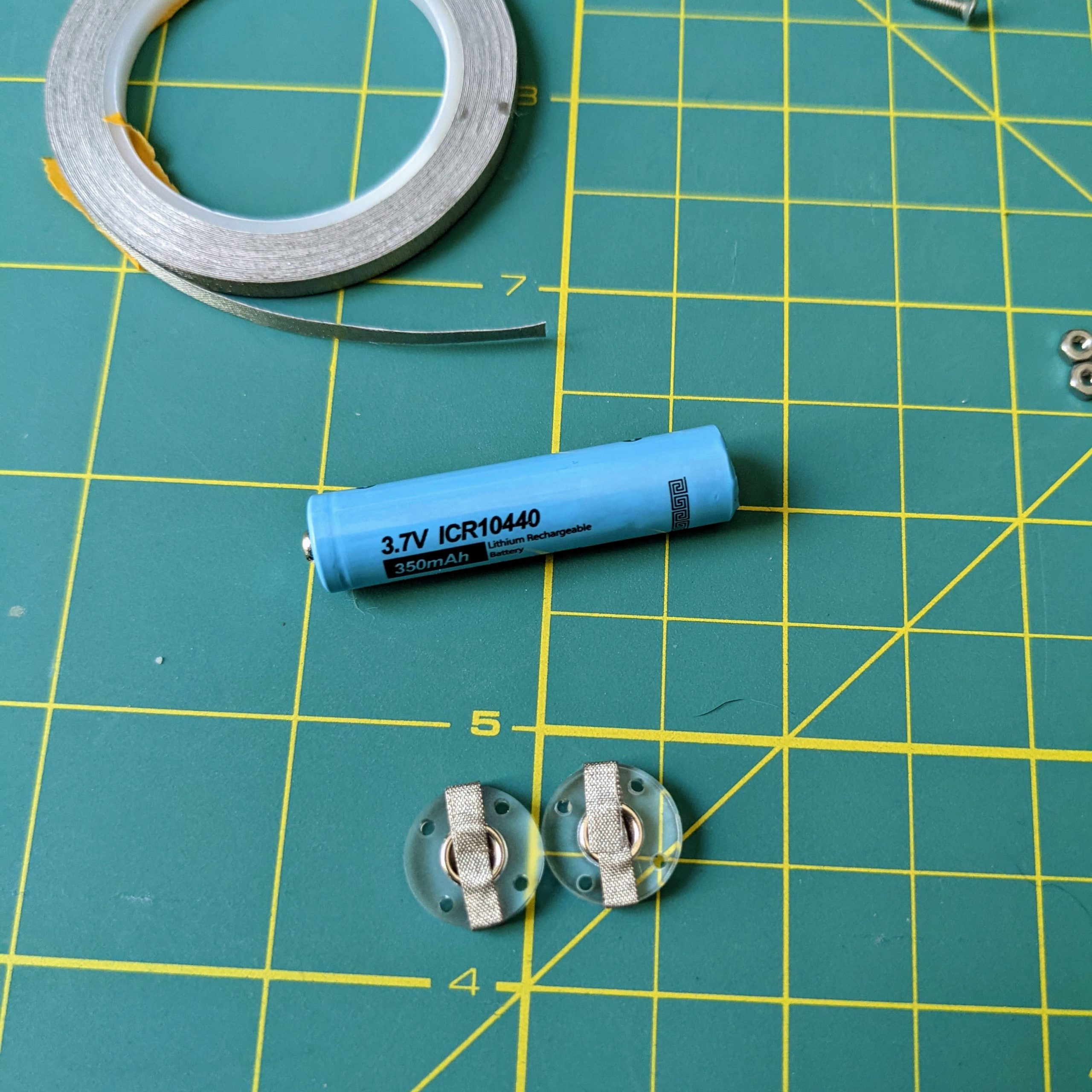
Select two countersunk magnets of opposite polarity and insert them into the center holes in the acrylic pieces. Wrap a bit of conductive tape around the disk to secure them in place. Be sure that the tape does not cover the small holes in the acrylic.
Step 3: Thread elastic through disks
Start with disks at the battery ends. Wide side of countersunk holes faces battery 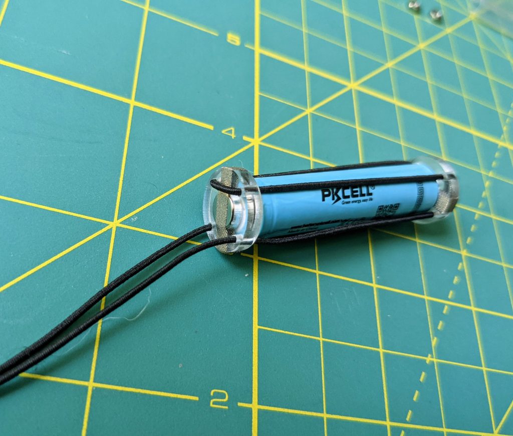
Thread the elastic back and forth through the small holes in each disk 
With moderate tension in the elastic, tie the ends in a double knot, and trim the excess


Place the disks at opposite ends of a battery. For both disks, be sure that the wide end of the countersunk holes is the end touching the battery poles. This allows the disk to sit flush at the positive end and ensures that the opposite ends of the battery holder have opposite polarities.
String the elastic back and forth between the two disks and pull it tightly enough that there is some tension in the elastic, but that it can also stretch more if pulled. When finished, tie the loose ends of the elastic cord into a double knot and trim any excess.
Step 4: Attach magnets to stranded wire
Cut two lengths of stranded wire and strip the ends 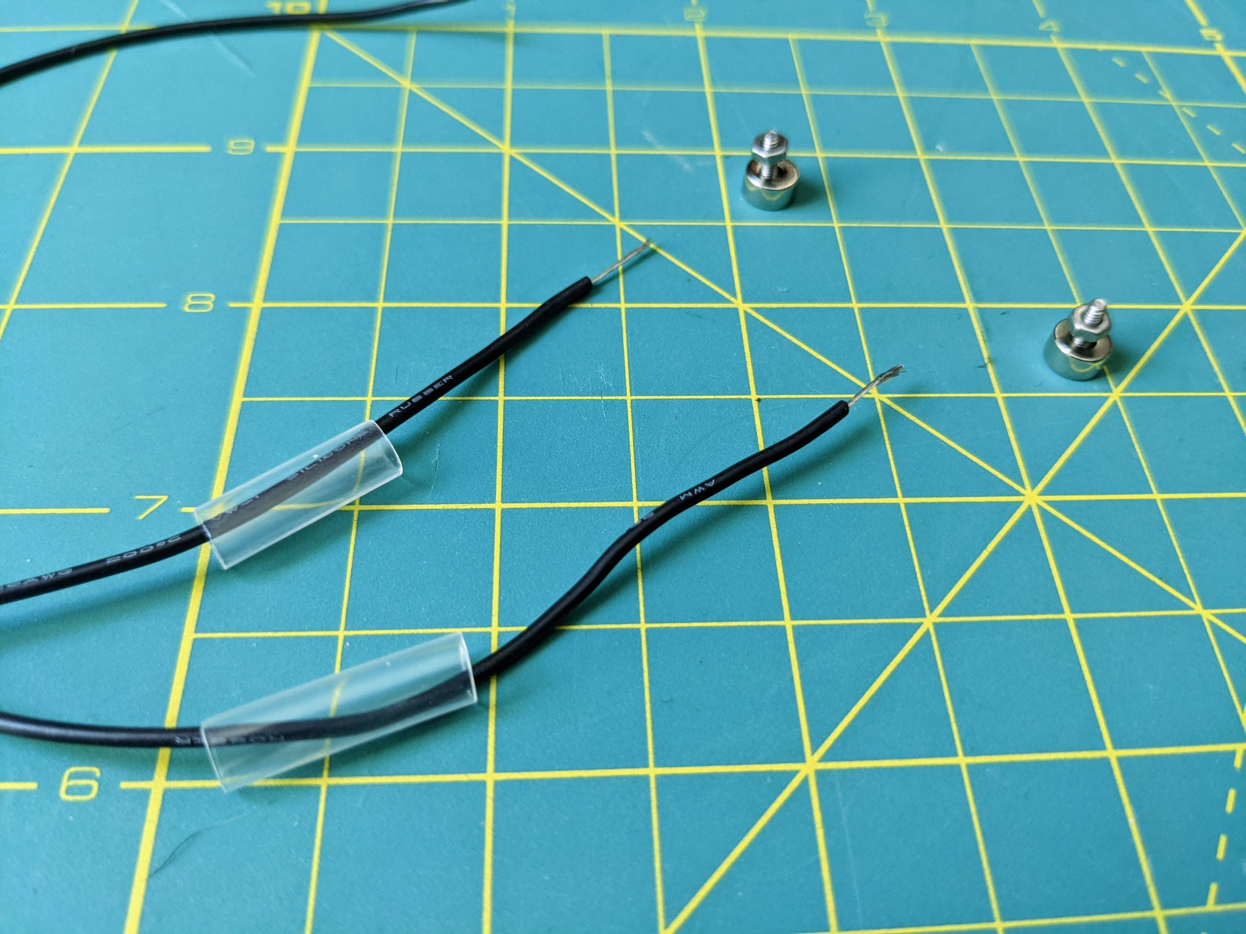
Place shrink tube over wire ends. Insert screws into countersunk magnets 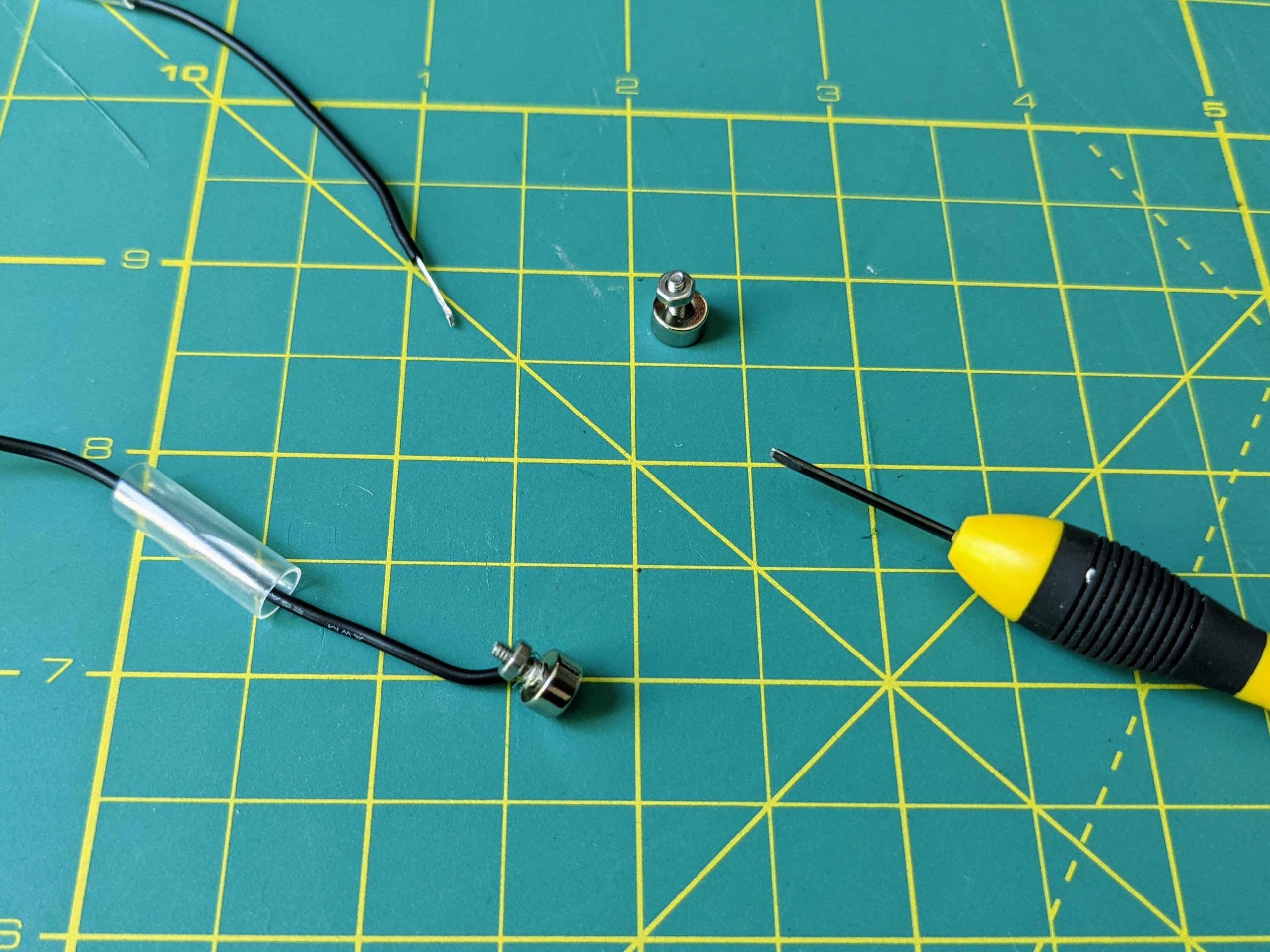
Wrap wire ends around the screw and secure it into place by tightening the nuts 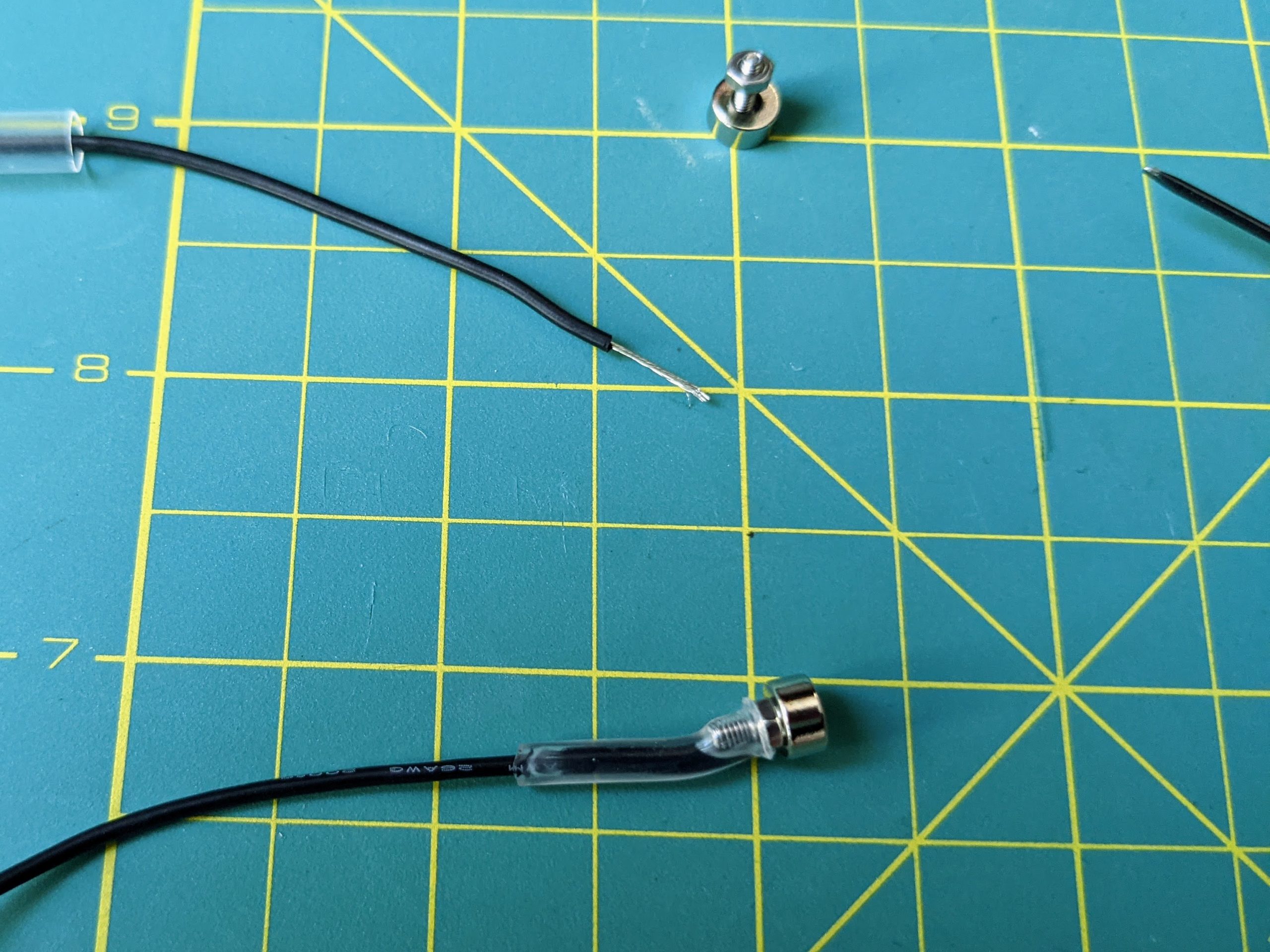
Heat shrink tube to secure wire to screw 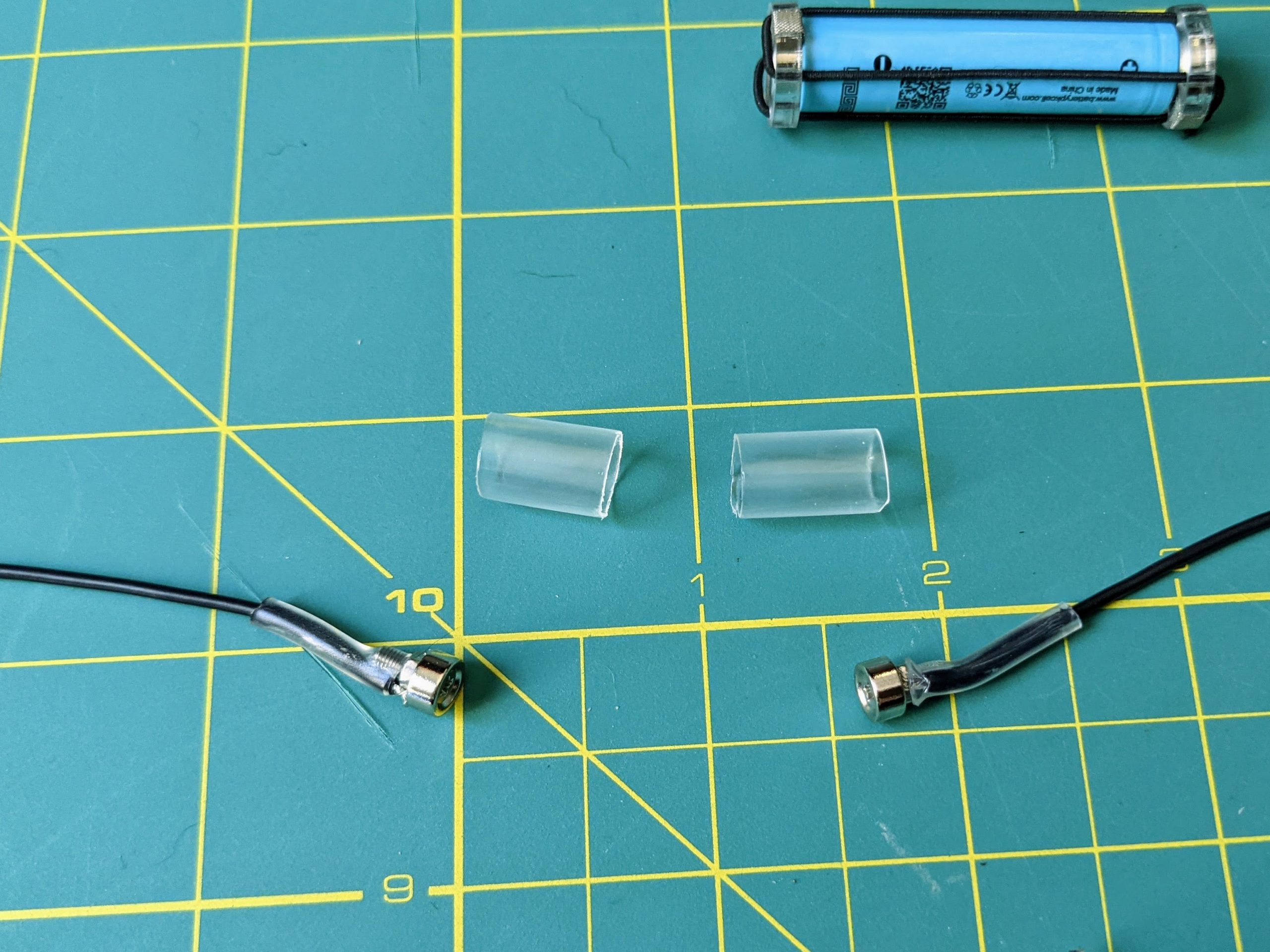
Add larger shrink tube around the magnet 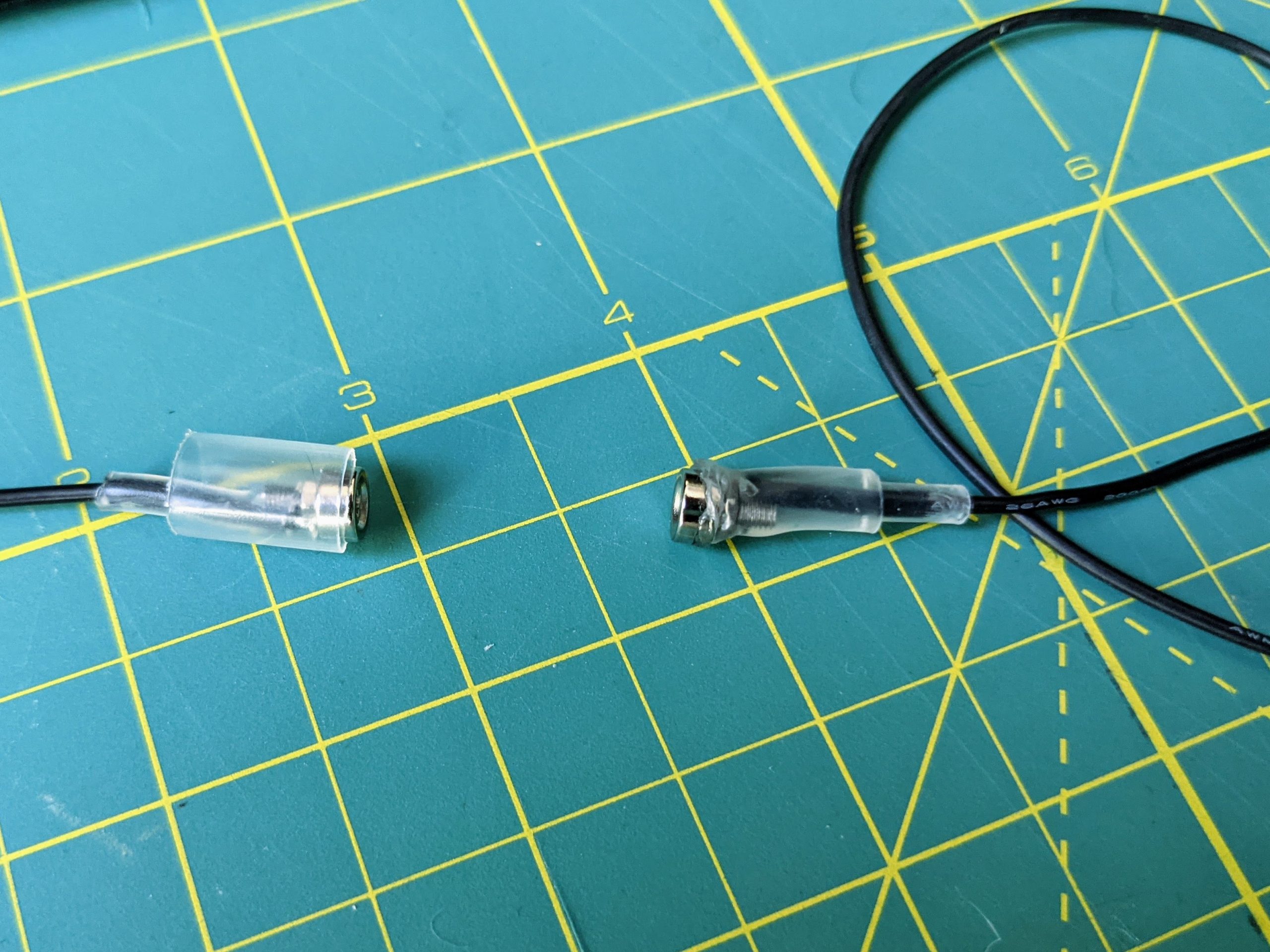
Figure out how long you want the wires to be for your wearable. One end of each wire will attach to the +/- power inputs of your electronics, and the other end of each wire connects to a magnet. The two remaining magnets have opposite polarity, and each will attach to a disk with the wide end of the magnet hole facing the disk. This will determine which magnet attaches to the positive/negative power wires. It is extremely important to get this correct or your power will be connected backwards.
Take each magnet and slide an M2 flathead screw into the wide end of the hole, and secure it in place with an M2 nut, but do not tighten the nut all the way yet.
Take the end of the power wire and strip about 1 cm of insulation from the end. Slide a piece of (about) 3/8″ shrink tube over the end of the wire. Wrap the uninsulated portion of the wire around the screw between the nut and the magnet, then tighten the nut to secure the wire. Slide the shrink tube up over the wire and the end of the screw, getting it over the nut, if possible, then heat to shrink and hold in place.
Allow the magnet to cool, then take a short piece of 1/2″ shrink tube and slide it over the magnet so that it runs from the midpoint of the magnet side to approximately the end of the previous piece of shrink tube, and heat it to shrink into place.
Step 5: Mark positive and negative disks
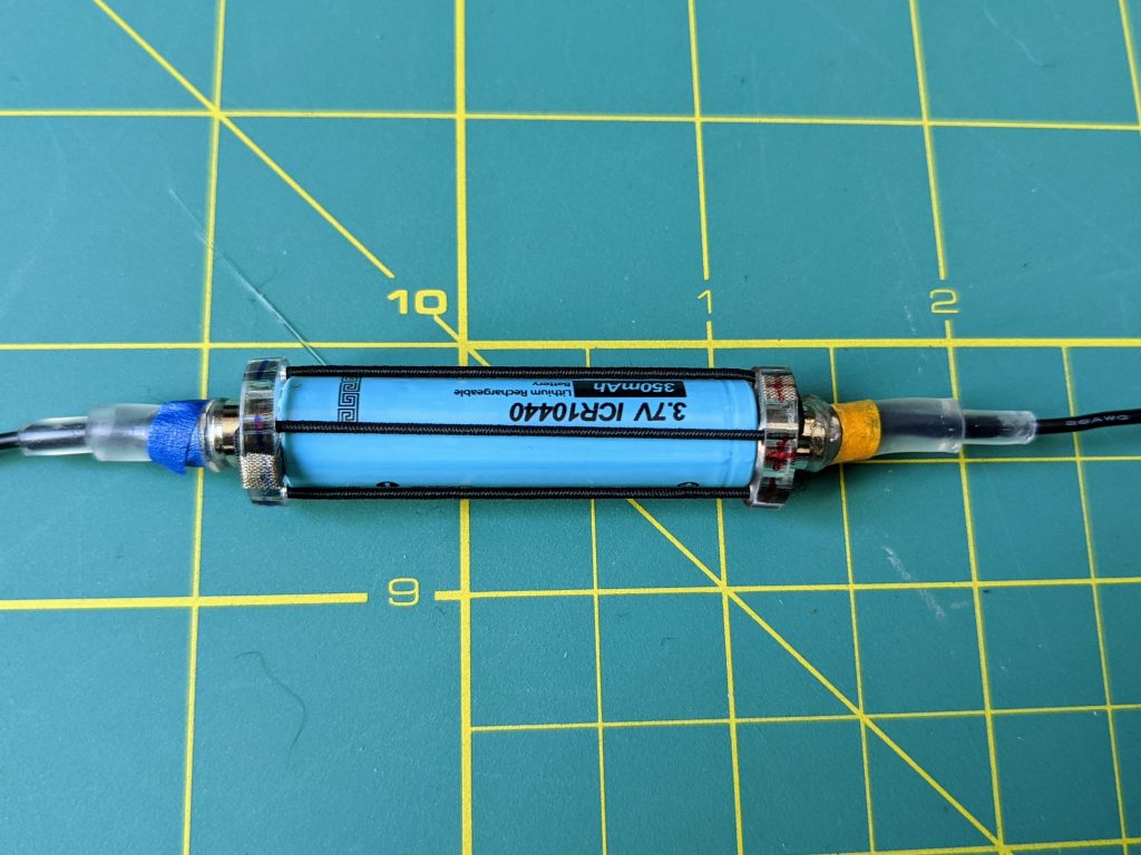
Before powering up your wearable, make absolutely sure that the polarity of all connections is correct. Place the elastic-connected end caps over the ends of your battery, with the wide side of the countersunk holes touching the battery. Make sure that each wire is attracted to one end cap and repelled by the other. Once you are certain that the positive power wire is attracted to the positive end cap, draw a “+” sign on the positive end cap with a sharpie, and a “-” sign on the negative end cap as well. Then, as long as you attach the correct end caps to the correct ends of the battery, the power wires will snap into place, and power your project.


Really great stuff! I love how this bypasses the problem of an embedded LiPo battery.
For the Fibonacci 64, are you using Adafruit’s Qtpy for the microprocessor or something else?
Also, can you comment on how you connect the battery to the circuit – i.e. directly through the USB 5V, or into the output side of the 3.3V regulator, or…?
Sorry for the belated response. The microcontroller is either a QTPy or a XIAO, I’m not sure which offhand. I run the current from the battery in through the controllers USB-C connector directly, using a USB-C male connector soldered to the wires from the battery, then inserted into the USB-C female connector.
Thanks for the deets! I bought the default built-up version of the Fibonacci 64 with a Qtpy – really gorgeous piece. Thinking about how to use it as a sort of Star Trek style CO2 level display. Faster the spin, the higher the level?
Thanks for a great idea. But… you do not need the elaborate design. You can solder a tiny neodymium magnet directly to the battery contacts (you must use an aggressive solder flux, like Stay-Clean, normally used for plumbing jobs, etc.). Use a wide heat shrink wrap tube to cover the entire battery, leaving about 1/2 inch of extra wrap at each end – this extra will shrink to the diameter slightly larger than the second tiny magnet that you will solder to stranded wire. Et voila!