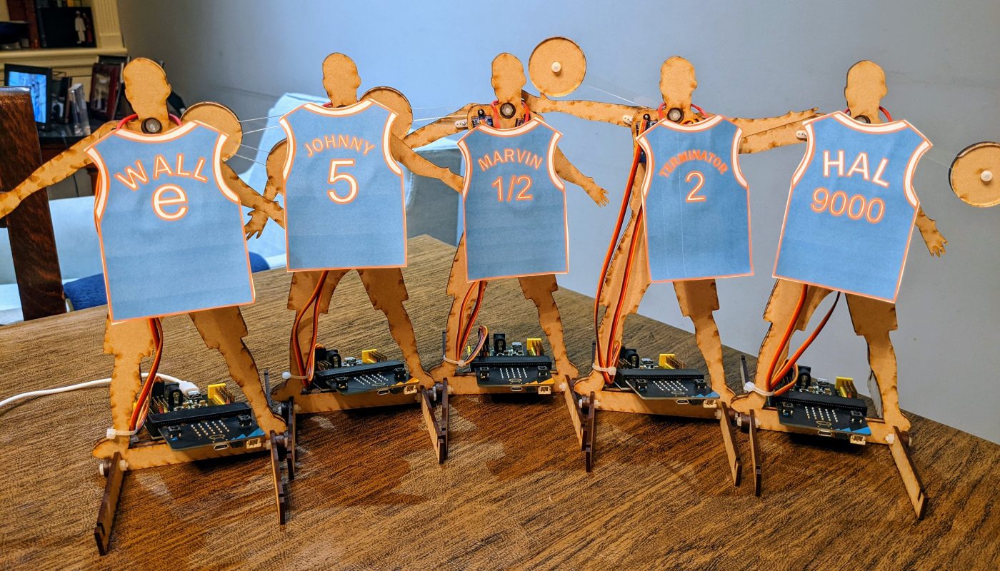


I designed this project for a special Code Club event at the Clippers basketball arena (follow this link to see a short video summary of the event). These bots are a fun way to learn to code micro:bits to control servo motors. The bot’s two motor-controlled arms can “toss” a basketball attached to a clear acrylic tether.
Materials
Components:
- (2x) Flanged ball bearings (3x10x4mm) like these
- M3 x 16mm screws
- (2x) 9g Servos
- micro:bit motor control board (to provide power to the motors and micro:bit separately). I used this one.
- power cable for the control board
- micro:bit microcontroller
- 1/8″ in wood sheet (opaque 1/8″ acrylic can work as well)
- Small piece 1/8″ clear acrylic
- (4x) 12mm M2 machine screws
- (4x) M2 nuts
- (5x) 12mm M3 machine screw
- (1x) 16mm (or longer) M3 machine screw
- (6x) M3 nuts
- (2x) 8mm machine screws that fit your servo gear (M2 or M2.5, usually, depending on your servo)
Tools:
- laser cutter or laser cutting service
- screwdriver
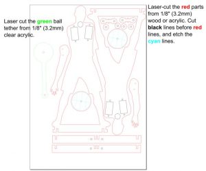
LaserCut the Sheet Materials:
Download the vector file from the link below the image. All pieces are in the file named “basketBotAcrylicOnly.svg.” Also, the wood and acrylic pieces are saved in two separate files. Follow the instructions in the file to cut the different color pieces from 1/8″ sheet wood and 1/8″ acrylic. Note that the cyan colored lines are intended to be etched.
Assembly
Insert Bearings and Motors
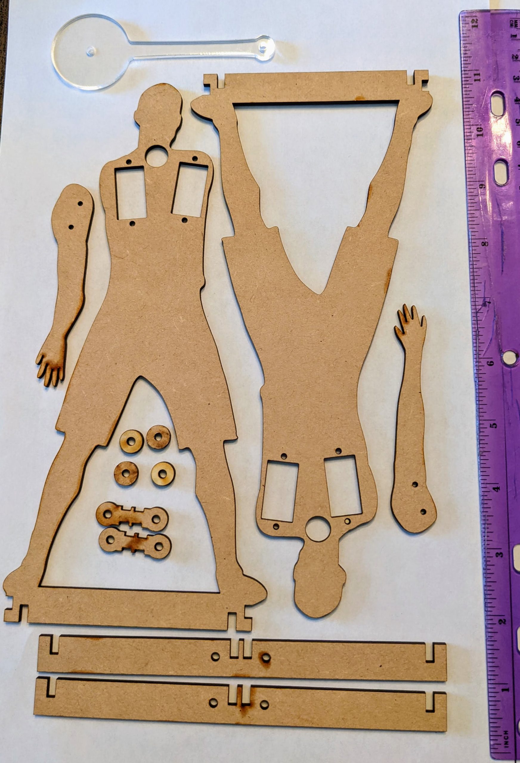
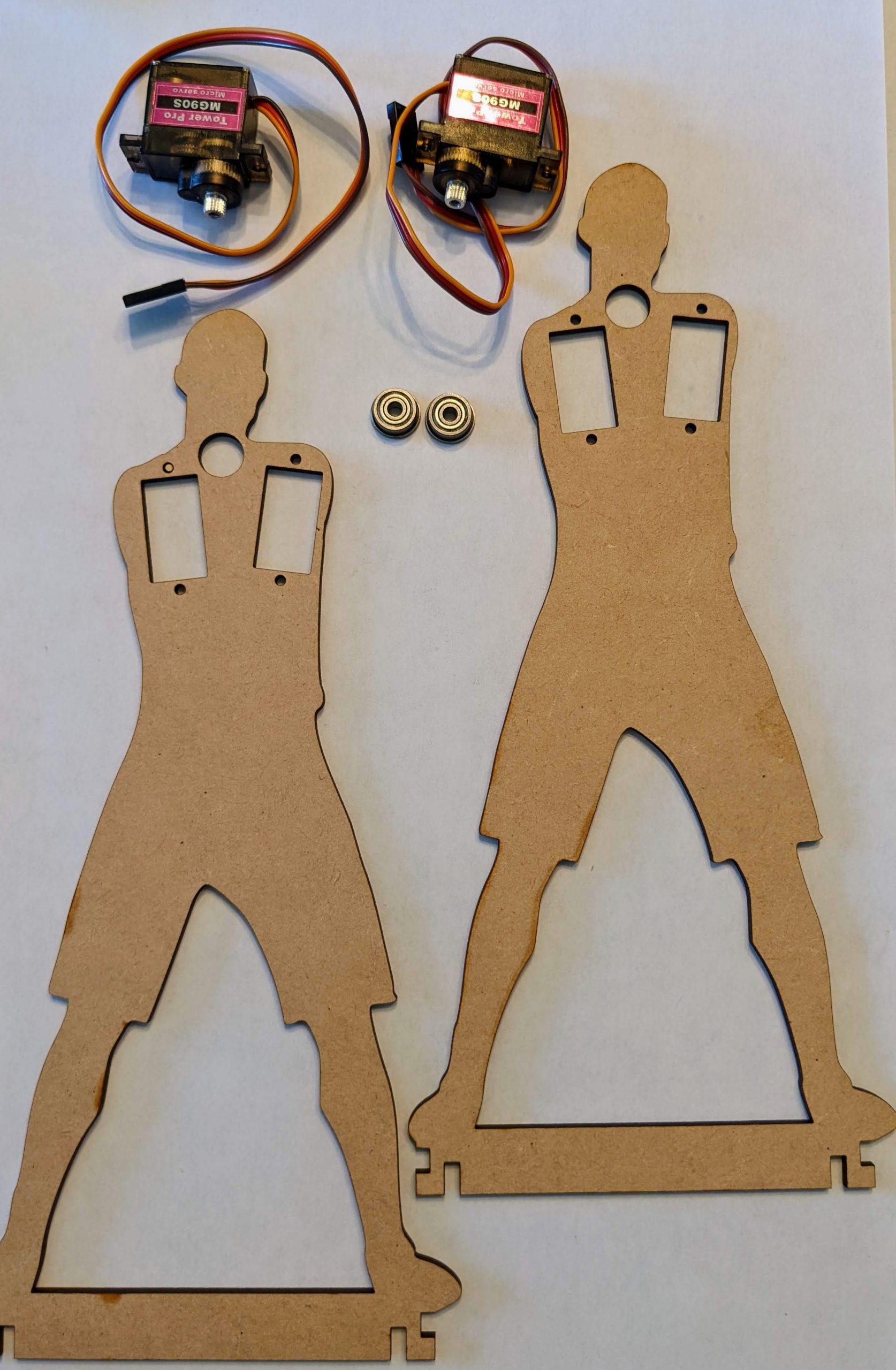
After cutting out the main pieces from 1/8″ wood sheet as shown at left, take the two body-shaped parts, gather the two bearings and two 9g servo motors. The build images show metal gear servos, because that’s what I had on hand, but standard plastic gear servo motors work just fine and are cheaper.
Place the two body-shaped wood pieces together so their shapes align. Decide which will be the front layer and which one will be the back layer.
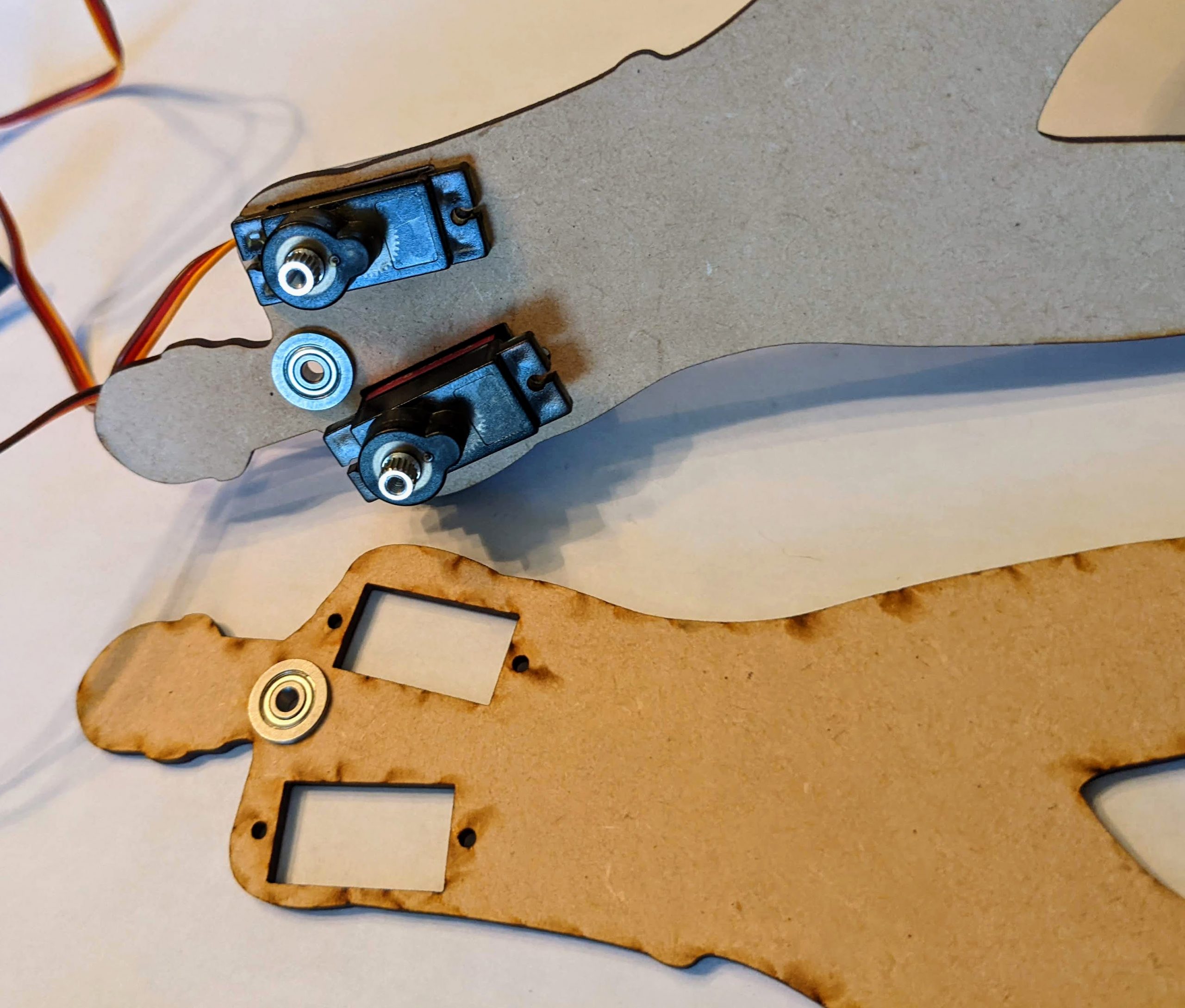


The bearings fit into the circular slots in the body so that the flanged parts sit in between the two wood pieces. The fit is snug, so gently push the narrower end of the bearing down into the wood piece as it sits flat on a table, and apply pressure with a book or some other flat object to insert it fully into the hole.
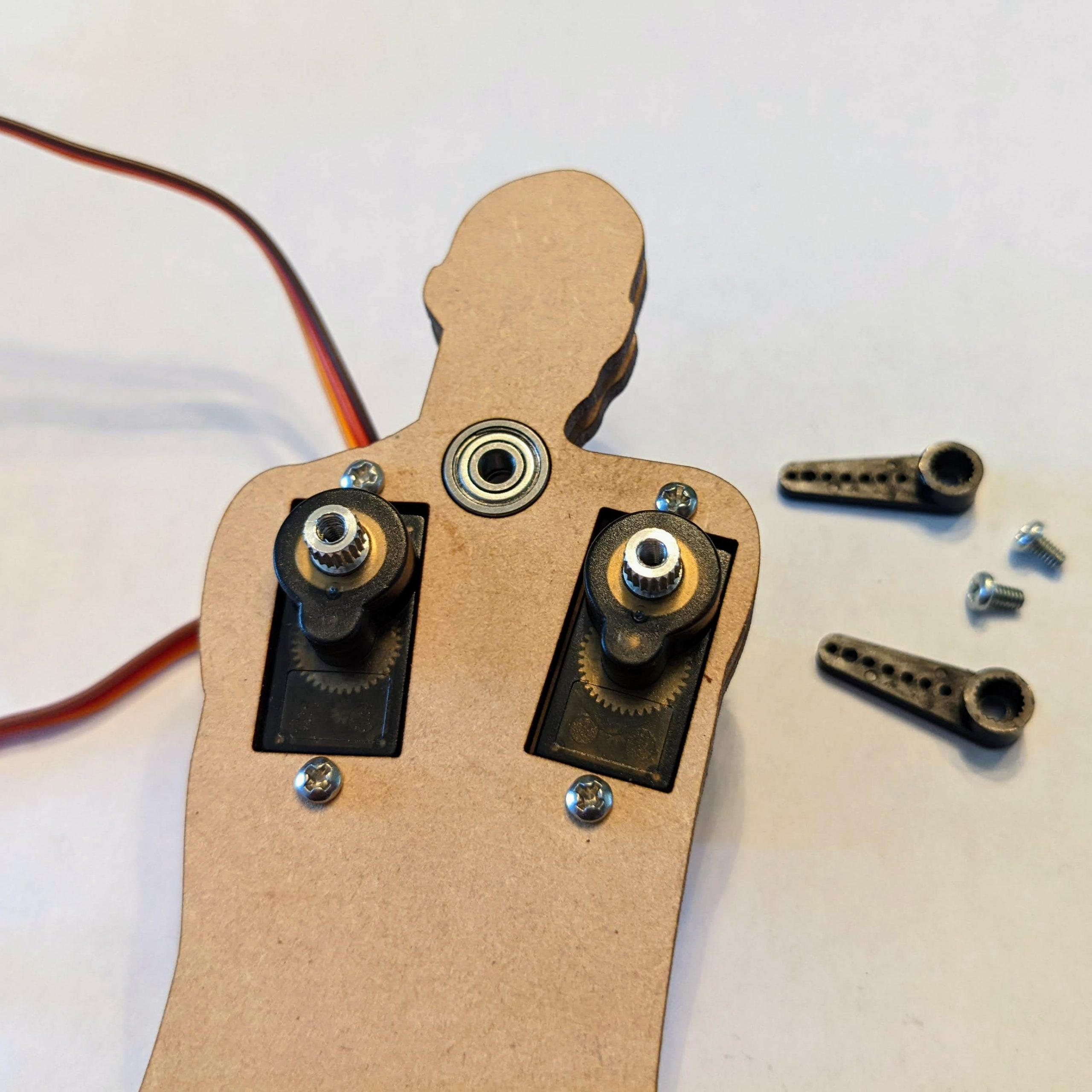
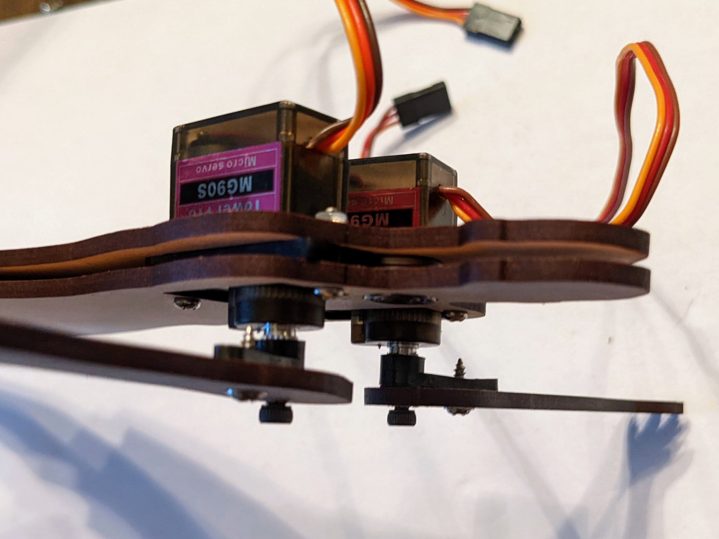
After inserting the bearings, take the back wooden layer and one of the servo motors. Hold the layer so that the flanged side of the bearing faces you and slide the servo connector cable down through a rectangular hole. Then place the servo down into the same hole with the gear connector located towards the top of the rectangular hole nearest the bearing. Repeat with the second 9g servo. Then place the top wooden layer over the first so that the servo “shelf” protrusions are sandwiched between the layers. Then use the four 12mm M2 screws and nuts to secure the layers together through the holes just above and below the servo motors.
Attach the Servo Horns and Bot Arms
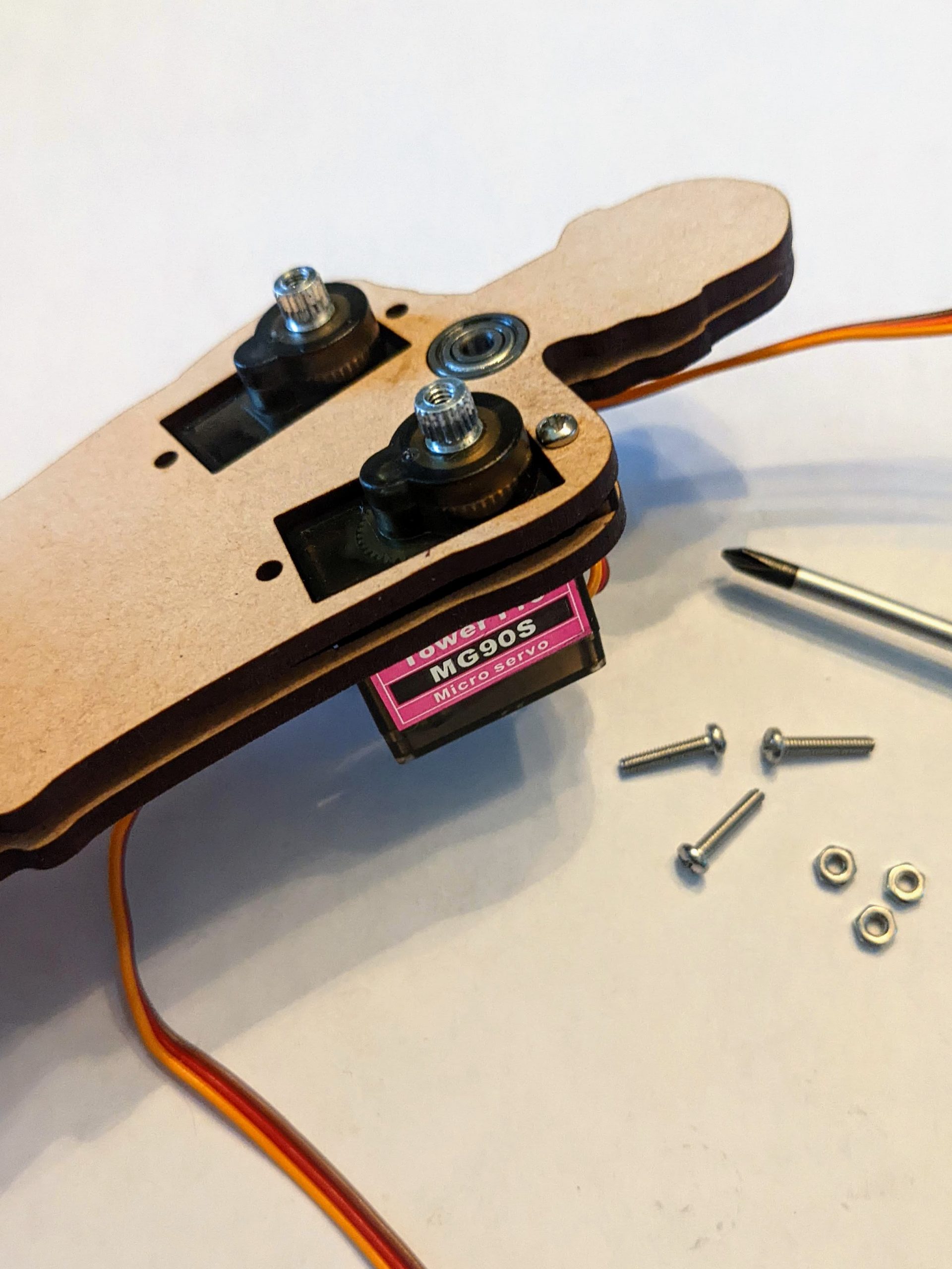
The single-sided servo horns are used to hold and move the player’s arms. Most 9g servos come with a variety of horn shapes as well as two pointy screws to pierce and hold the horn and a flat-ended screw to secure the horn to the servo. The flat ended screw that came with my servo wasn’t long enough to pass through the wood piece before screwing into the servo motor, so I had to find other screws that would fit. I found M2.5 8mm screws worked for the metal gear servos, but M2.0 8mm screw fits standard 9g servos best.
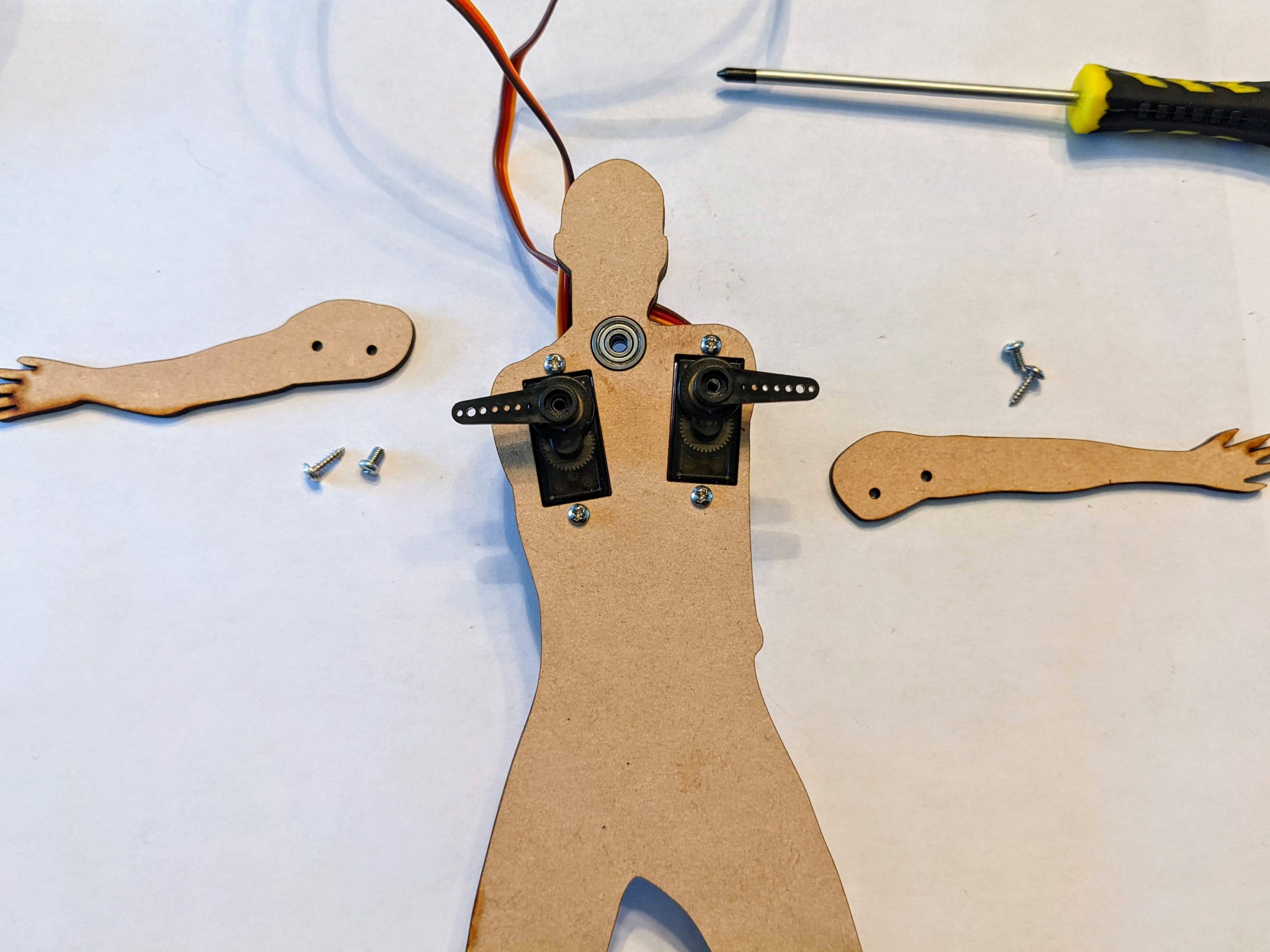
Before inserting the screws, orient the main servo gears to their middle position. You can do this by slotting the servo horns over the gear, then rotating them manually over their full range of motion to be sure that the horn is pointing straight up or straight down at the stopping points. If that’s not the case, lift off the horn and place it over the gear at a different angle and repeat the process. Once the horn is placed so that the servo horn is vertical at both rotation endpoints, manually rotate the servo gear until the horn is in the middle position, then lift the horn off of the gear.
Next, take one of the wooden laser cut arms, a single-sided servo horn, one of the pointy servo screws and the 8mm (M2 or M2.5, depending on which one fits) machine screw for the main servo gear. Slide the machine screw into the hole to hold the center of the servo horn in place, and, using a screwdriver, drive the pointy screw through the wood arm piece from the top and into one of the small holes on the servo horn. It will take a bit of force, and you will have to hold the horn to the wooden arm until it they are securely screwed together.
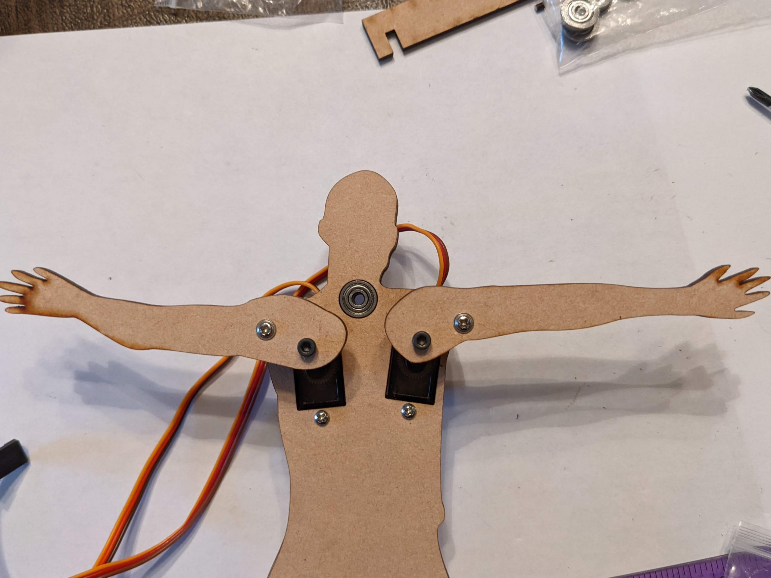
After the horn is securely attached to the arm, place the arms over the servo so that the gear slots into the horn, and the arms are extended horizontally as shown, and use the machine screw to secure the arms to the servos. If you have flush cutters, you may want to (carefully – use eye protection!) cut the pointy ends off of the servo screws.
Attach the Basketball
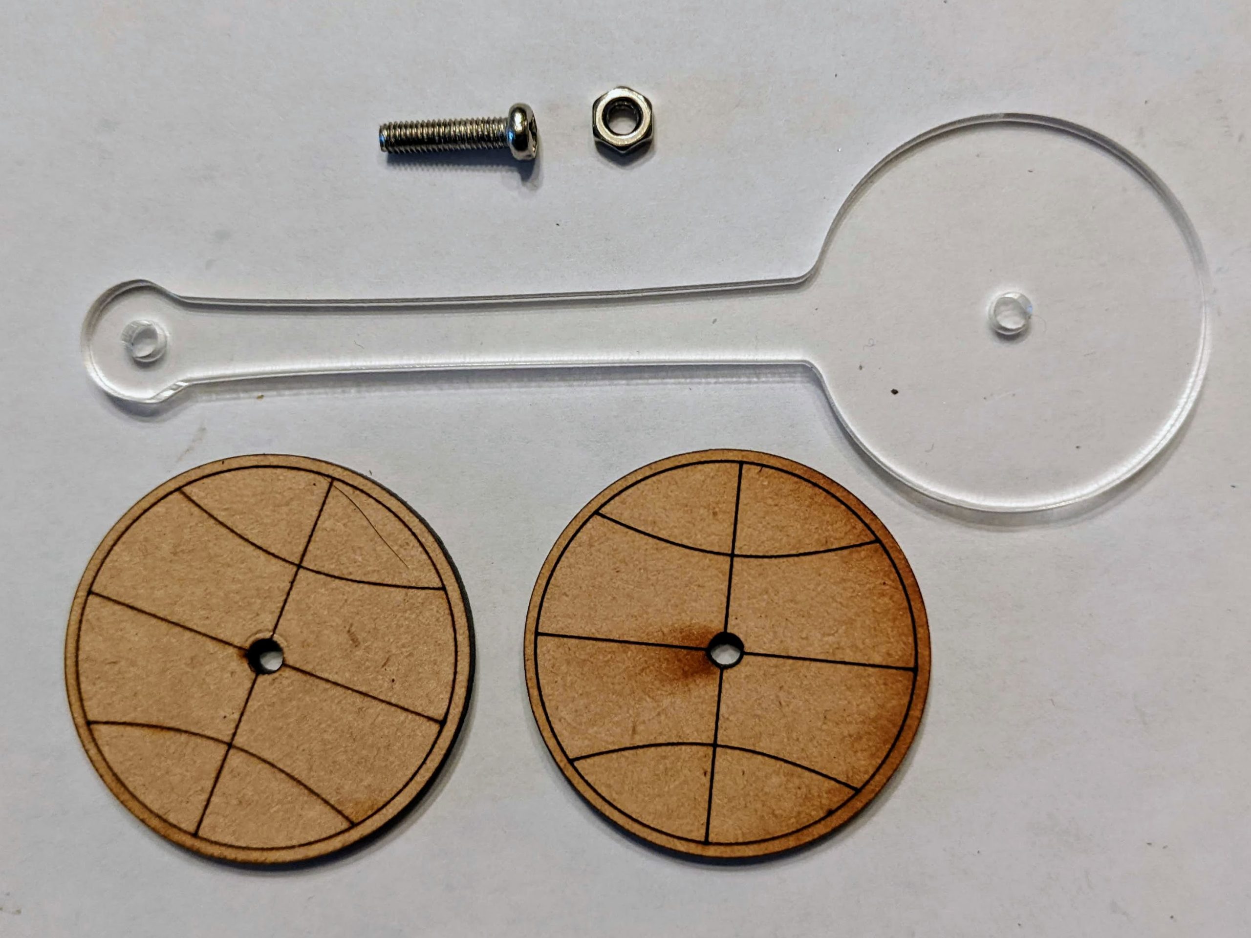
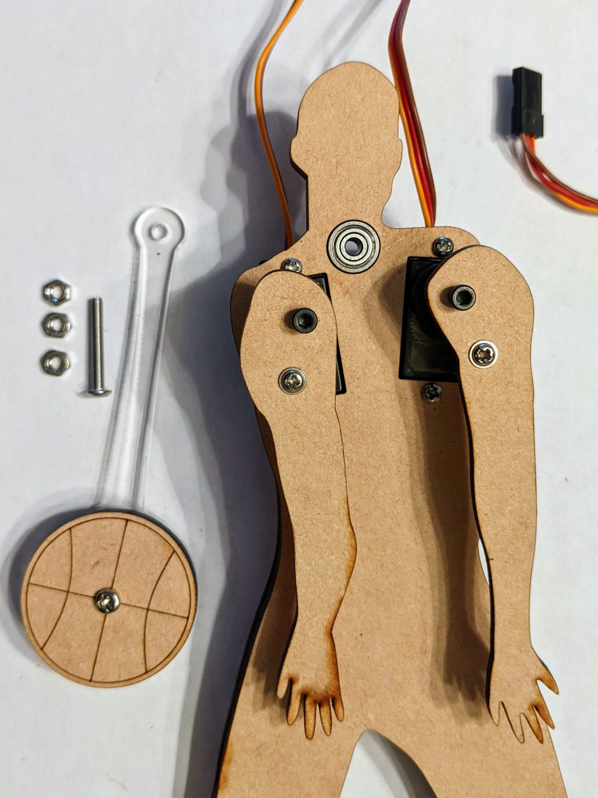
Now that the arms are secured, gather the two laser cut basketballs, the acrylic basketball “tether,” one 12mm M3 screw, the 16mm or longer M3 screw and four M3 nuts. Manually rotate both of the bots arms until they point downward, to keep them out of the way for this next step.
Next, secure the basketballs to the tether using the 12mm M3 screw and nut through the center holes. Both basketballs are secured on the same side of the tether, stacked on top of one another.
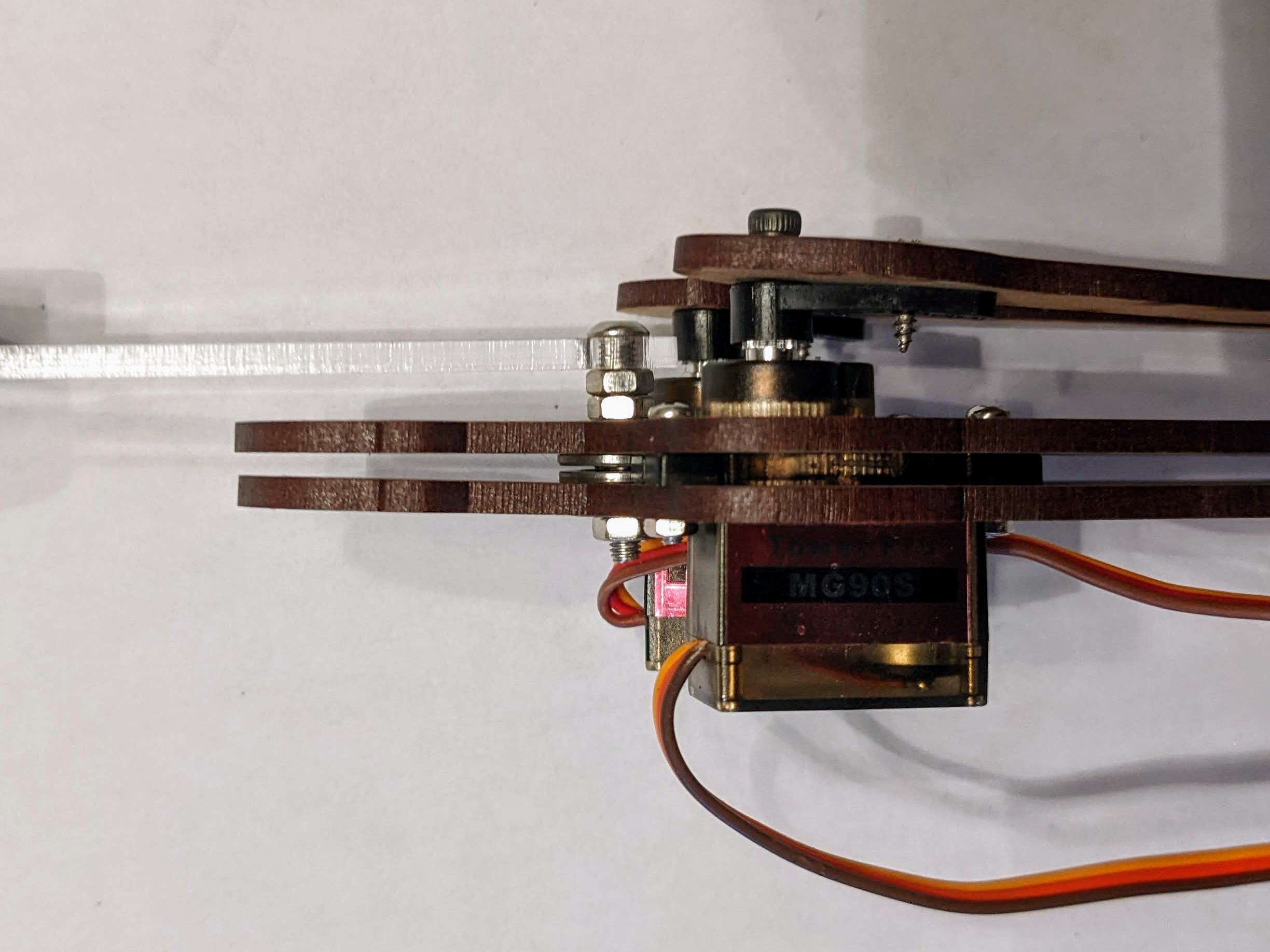
Now place the 16mm (or longer) M3 screw through the hole at the small end of the tether. The screw head should be on the same side of the acrylic tether as the wooden basketballs. Fasten two M3 nuts on the other side of the screw. This will hold the basketball in the correct position for the arms to push it. After both M3 nuts are secured, slide the end of the screw through both of the bearings from the front of the bot. Secure the screw behind the back bearing with the remaining M3 nut. The tether should easily pivot on the screw, allowing the ball to travel in an arc back and forth between the bot’s arms.
Attach the Base
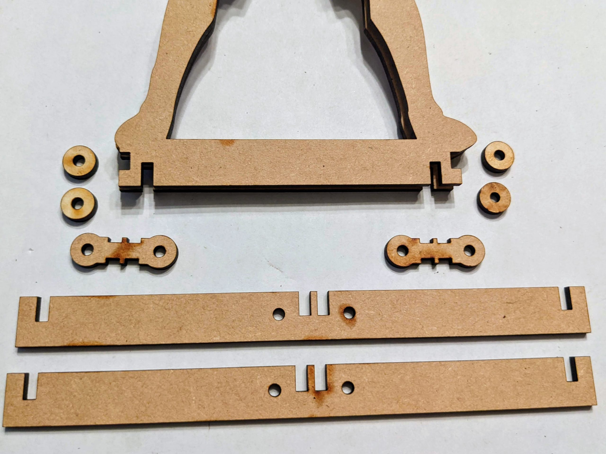
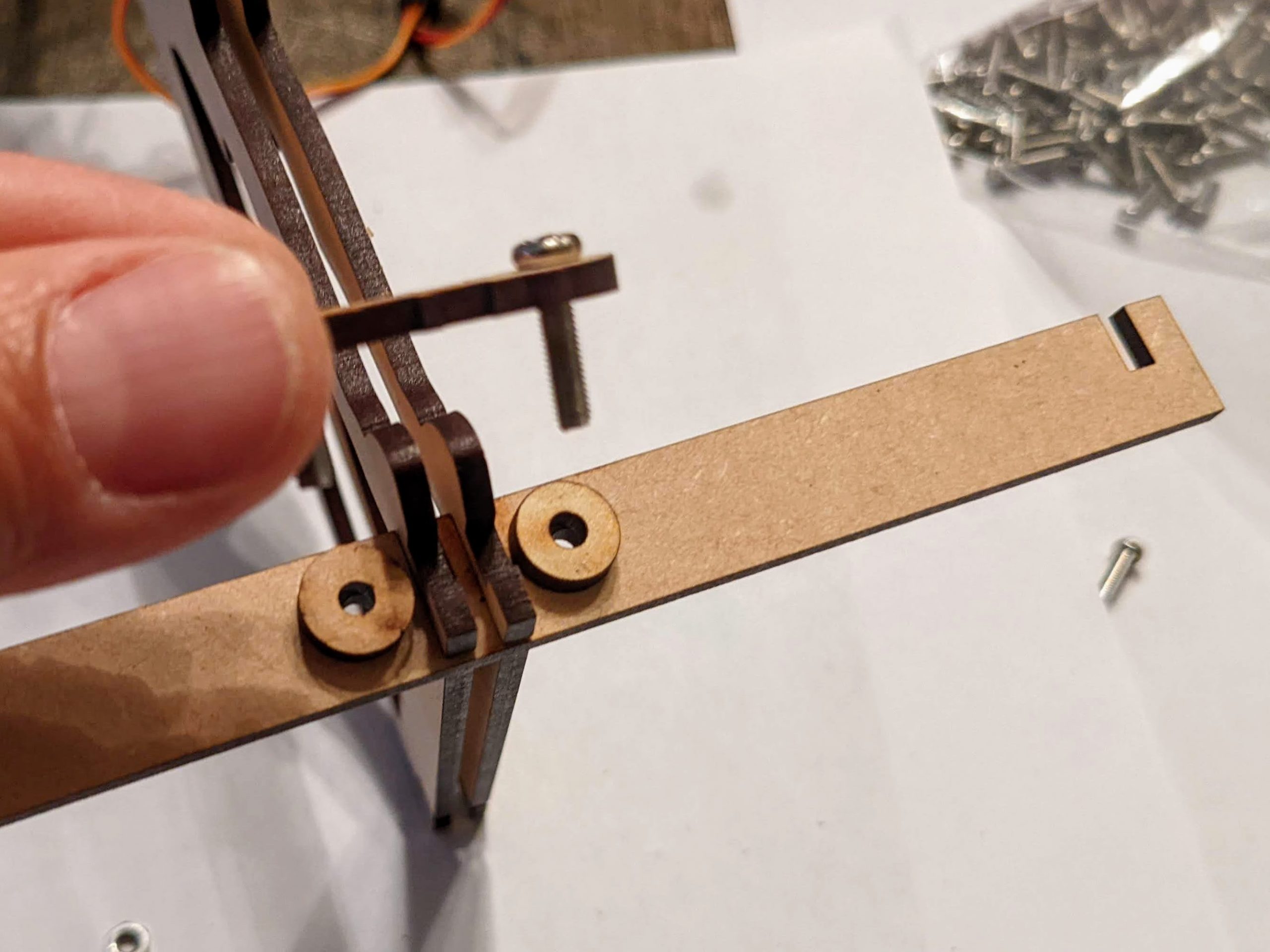
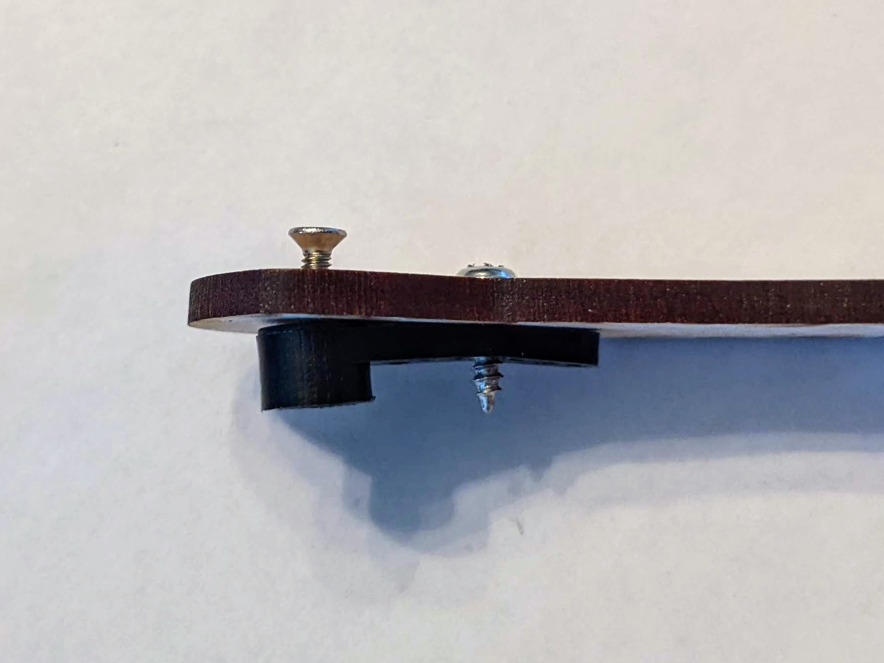
Gather the remaining wooden pieces shown in the first image above. The two long rectangles wtih notches form the base that allows the bot to stand freely. You will need a total of four 12mm M3 screws and nuts to secure the base pieces. Take one of the base pieces and slide the center two notches upwards into the notches near the bot’s feet as shown in the picture at right. Lay the bot on its side so that the long base piece rests sits horizontally. Place one circular spacer over each hole in the base piece as shown, then slide two of the M3 screws through one of the “figure 8” shaped pieces. Lower the “figure 8” piece over the spacers and carefully insert the nuts through the spacers and the the holes in the base piece. Secure three wooden layers together by attaching M3 nuts to the screws. Now repeat this operation for the other base piece. Your bot is now fully constructed, and should stand freely.
Programming Basket:Bot
To code the basket:bot, you will need to attach your micro:bit (or other controller) to the bot’s two servo motors. I used a micro:bit extension board that allows the motors to be powered separately from the micro:bit. Without the extension board, it is difficult to connect Power/Ground/Signal from each motor to the mciro:bit. There are a number of micro:bit motor control boards on the market, and any of them should work fine with this project.
Connect each servo motor to the control board, and attach the micro:bit. In my example I connected the servos to miocro:bit pins 12 and 13. Click this link to view and edit the micro:bit code to control the basket:bot’s arms with the micro:bit buttons A and B.
I wrote a set of instructions to guide students through writing the code for basket:bot. You can view and dowload a PDF version of the instructions at the end of this post, or download an editable Word version from this link.