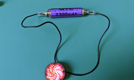
This build was inspired by a teacher whose students were having difficulty soldering “skinny” led strips for their projects. The adjustable jig is designed to hold various sizes of LED strips and wires in the best position to solder them together. A small silicone strip, cut from a wristband, provides a heat resistant surface for the soldering.
Using the Jig:
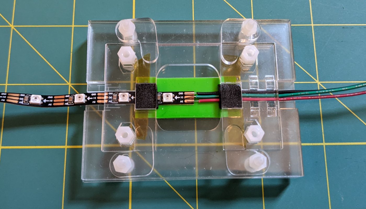
The jig is made from four layers of laser cut acrylic. One of the layers consists of two sliding pieces, with a gap between them. These pieces can move to accommodate and hold LED strips of different widths. There are tiny laser-cut wire guides as well which can be swapped into position to hold wires of different sizes with different spacing. The video below shows how the guide spacing is adjusted and how the LED strip and wires are inserted and secured:
Materials:
- Components:
- 1/8″ (3.2 mm) Acrylic Sheet
- 1/16″ (3.2mm) Acrylic Sheet
- 4 x M3 Nylon Hex Standoff, 10mm (or a bit longer) + 6mm (e.g. these ones)
- 4 x M3 Nylon Screws, 16mm or longer
- 8 x M3 Nylon Nuts
- 1 Silicone wristband (like these) or cuttable silicone mat
- small piece of thin, strongly adhesive tape. I used 1 mil Kapton tape
- small piece of 2mm adhesive EVA foam – or 2mm EVA foam and a really strong double-sided adhesive tape
- Tools
- Laser cutter (or laser cutting service)
- Screwdriver
Design Files
The downloadable SVG files in the link above are to be cut from 1/8″ (3.2mm) and 1/16″ (1.6mm) acrylic. There are four layers in the jig. The top and bottom layers are from 1/8″ acrylic, and the middle two layers are 1/16″ acrylic. The text in the design file tells you which layers are to be etched (scored) and which layers are to be cut.
Assembly
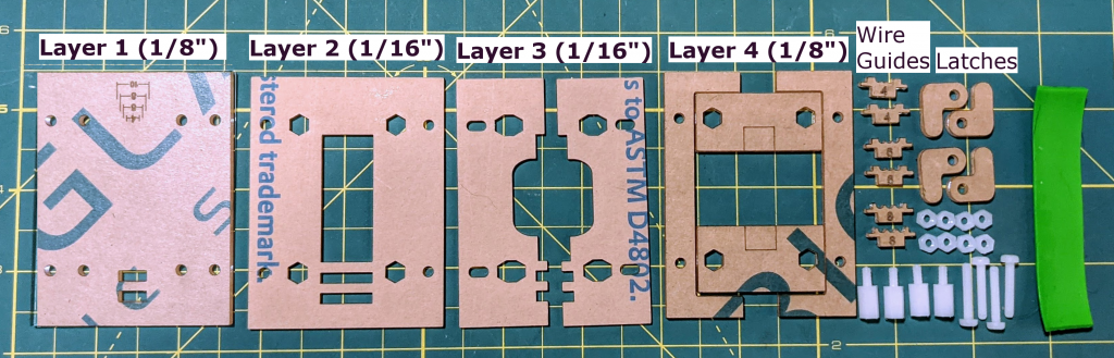
Once you’ve cut the pieces for the layers shown above, peel off any protective paper, and assemble the jig from the bottom layer (Layer 1), proceeding upwards. The wire guide pieces are very tiny, so be careful not to lose them when removing them from the laser cutter bed.
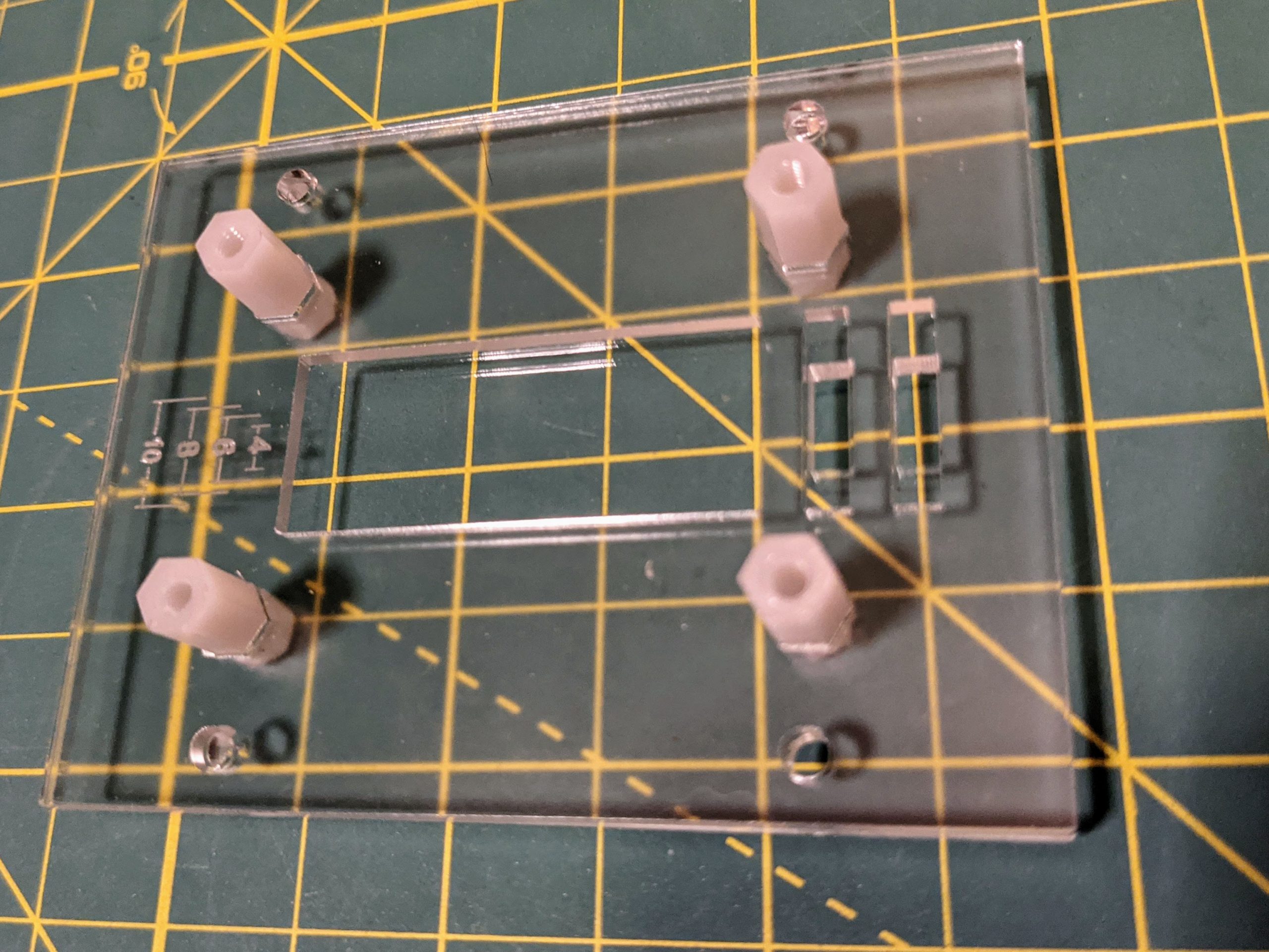
First take the bottom two layers, the four nylon standoffs and four M3 nylon nuts. Stack the thin acrylic Layer 2 on top of Layer 1, place a standoff so that it fits into the hexagonal hole in Layer 2 and the screw portion of the standoff passes through the hole in Layer 1. Screw a nut to the bottom of the standoff to secure it, and repeat with the other three standoffs as shown.
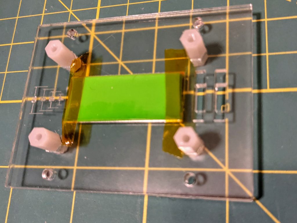
Next, cut a section from the silicone wristband that just fits into the rectangular cutout in Layer 2. Use two small pieces of Kapton tape secure both ends of the silicone strip as shown above.
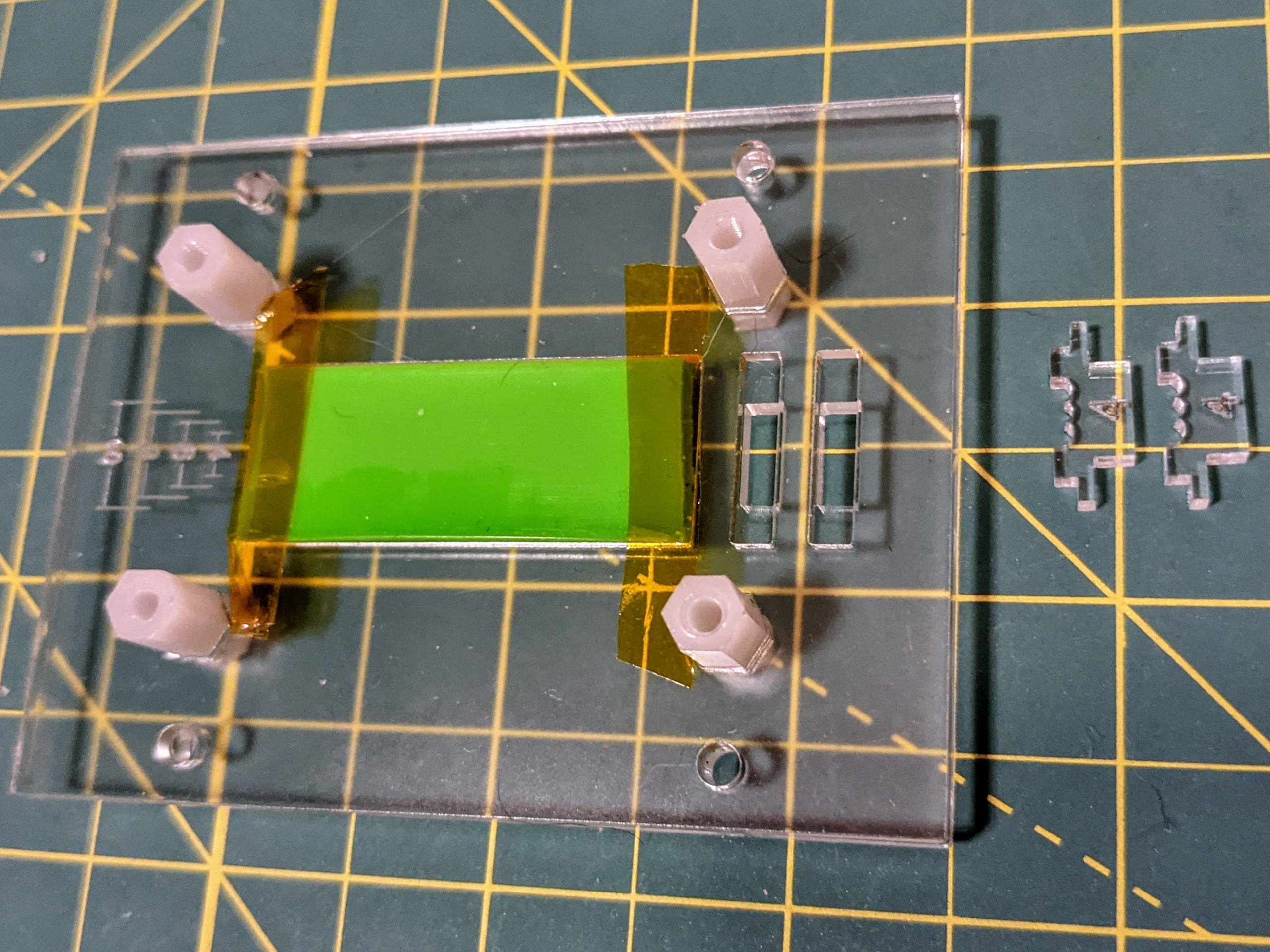
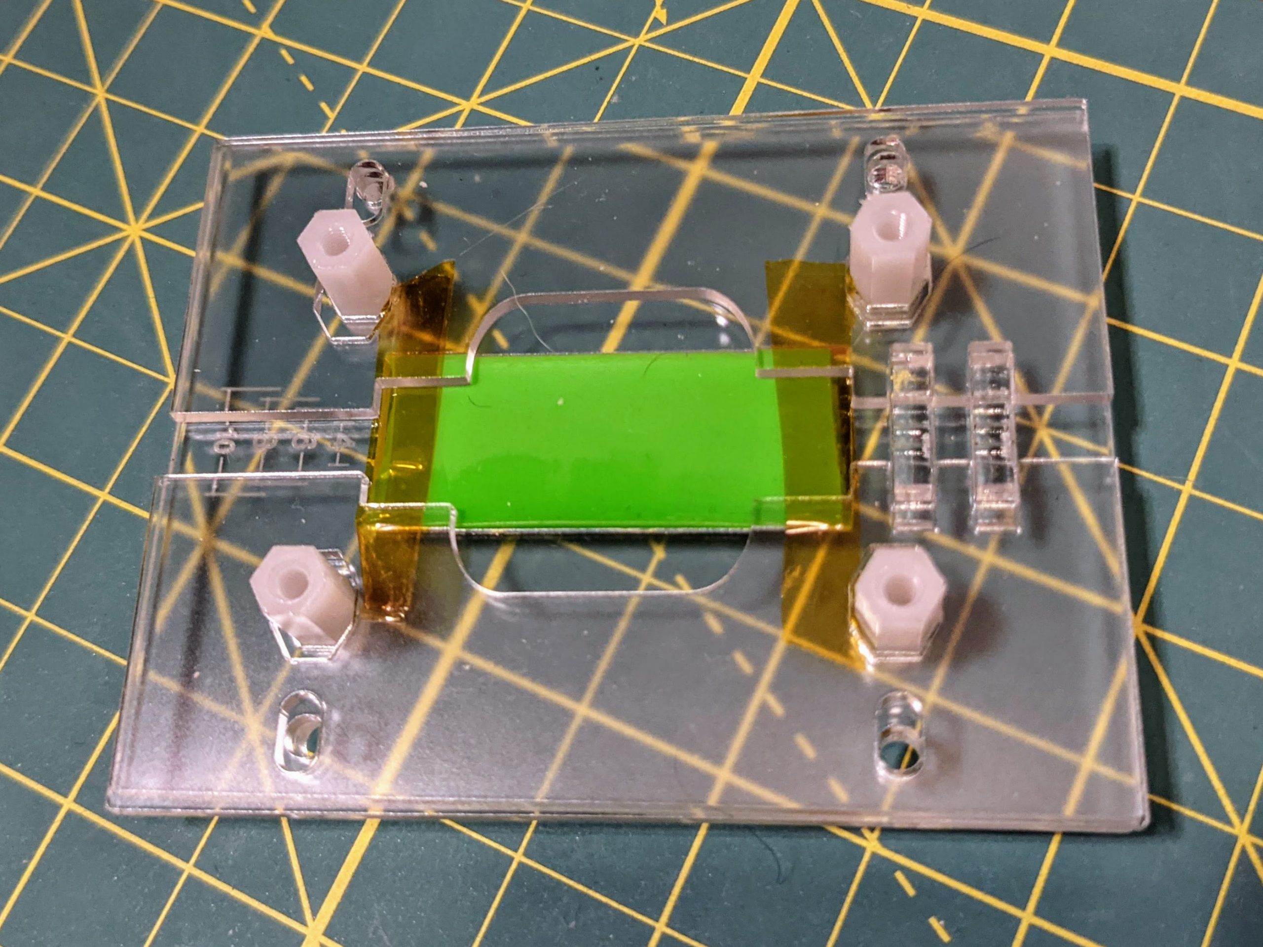
Insert the wire guides with the desired spacing into the two parallel slots, then place Layer 3 (Which consists of two separate pieces) over the top of Layer 2.
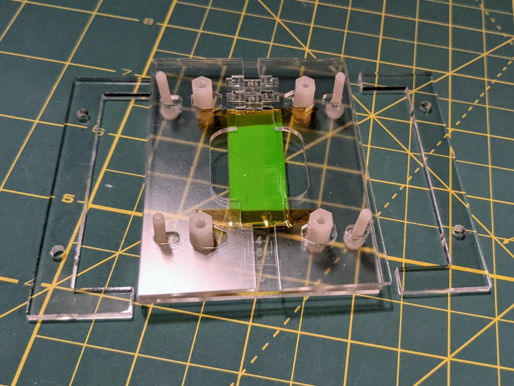
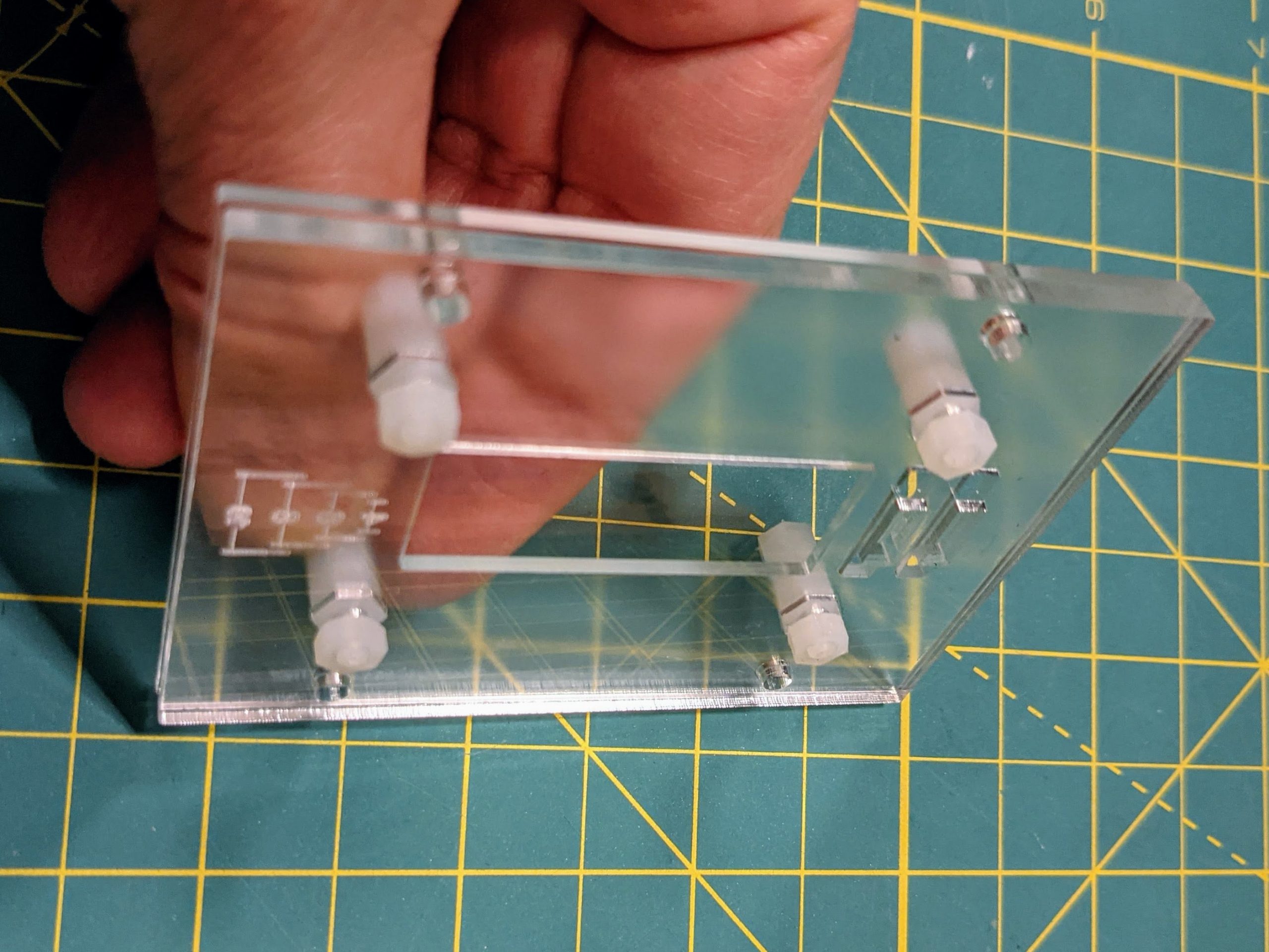
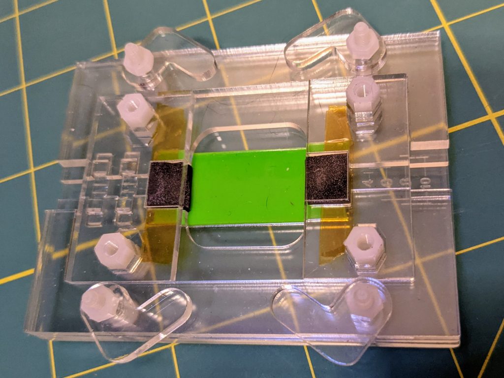
Insert the four long screws, pointing upwards, into the jig. Place the outer rails of the top layer over the screws. The pieces are not symmetric, so if the outer edges don’t align with the rest of the jig, place the rails in a different orientation. Then place the four latches over the screws as shown in the second picture above and secure in place with the remaining four M3 nuts. Tighten the nuts enough that the latches don’t wiggle easily, but can still be rotated into different positions.
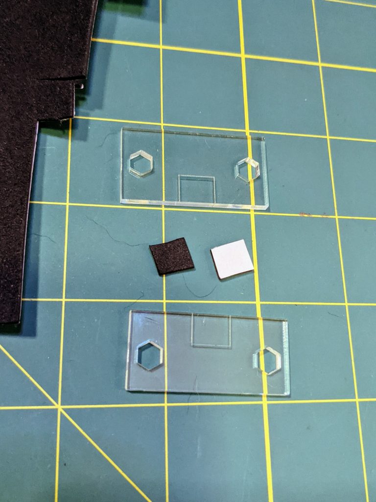
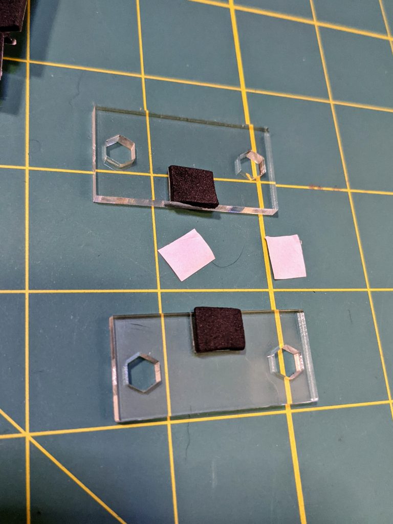
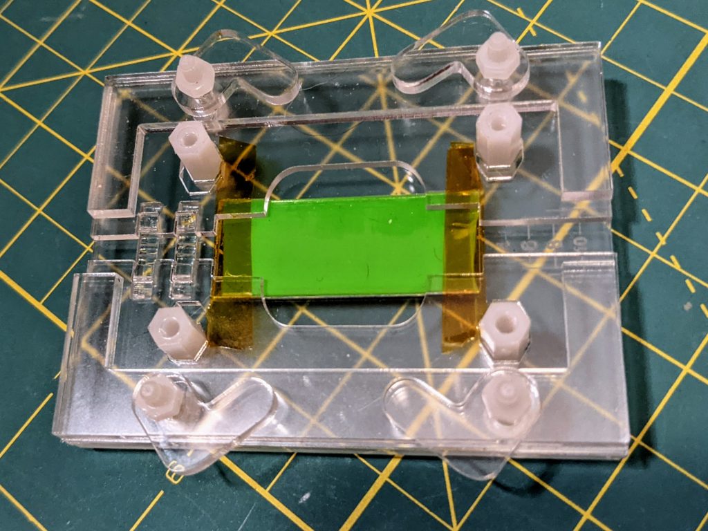
Next, take the two remaining acrylic cover pieces and the 2mm adhesive foam. Cut small rectangles (8mm x 10mm) of foam that fit completely inside the etched boxes on the cover pieces. Be sure that the foam doesn’t extend outside the etched area, or it will interfere with the ability to clamp down on the LED strip and wires. Stick the foam to the acrylic pieces, inside the etched outline.
Place the cover pieces, foam side down, over the standoffs so that they fit between the guide rails on the top layer. You may have to wiggle the rails a bit, but the pieces should fit so that they sit at the same level as the outer guides. After this step, the assembly is complete.
Using the Jig
Adjusting the LED Strip Width
You may adjust the spacing to accommodate LED strips of different widths. To do this, slightly loosen the nuts holding the latches in place and use your fingers to slide the pieces of Layer 3 inwards or outwards so that the guide for LED strip is wide enough to hold it but not soo wide that the strip wiggles around. When the spacing is good, tighten the nuts again.
Changing the Wire Guides
The different sized wire guides have slots with different spacings to position wires best for LED strips of different widths. To remove the wire guides, simply remove the two cover pieces from the top layer, turn the jig over until the wire guides fall out of their slots. Then turn the jig right side up, place the new wire guides in the slots, and replace the cover pieces.
Inserting LED Strips and Wires
The video at the beginning of this guide shows how to use insert and secure the LED strips and wires. Once the guide is adjusted to the width of the LED strip, you can insert the strip it by lifting the cover piece slightly and sliding the strip into the slot underneath the cover piece. Once the strip is in position, press down on the cover piece so that the foam secures the strip in place and rotate the latches to hold the cover down.
Similarly, align the wires in a row and slide them through the side of the jig with the wire guides. Once they are positioned properly, press down on the cover piece and rotate the latches into place to hold it down.
Accommodating Thicker LED Strips
If the LED strip is too thick to fit into the slot under the cover piece, you can laser cut additional small shims to sit underneath the latches. This will allow you to latch the cover piece in place at a slightly higher position.