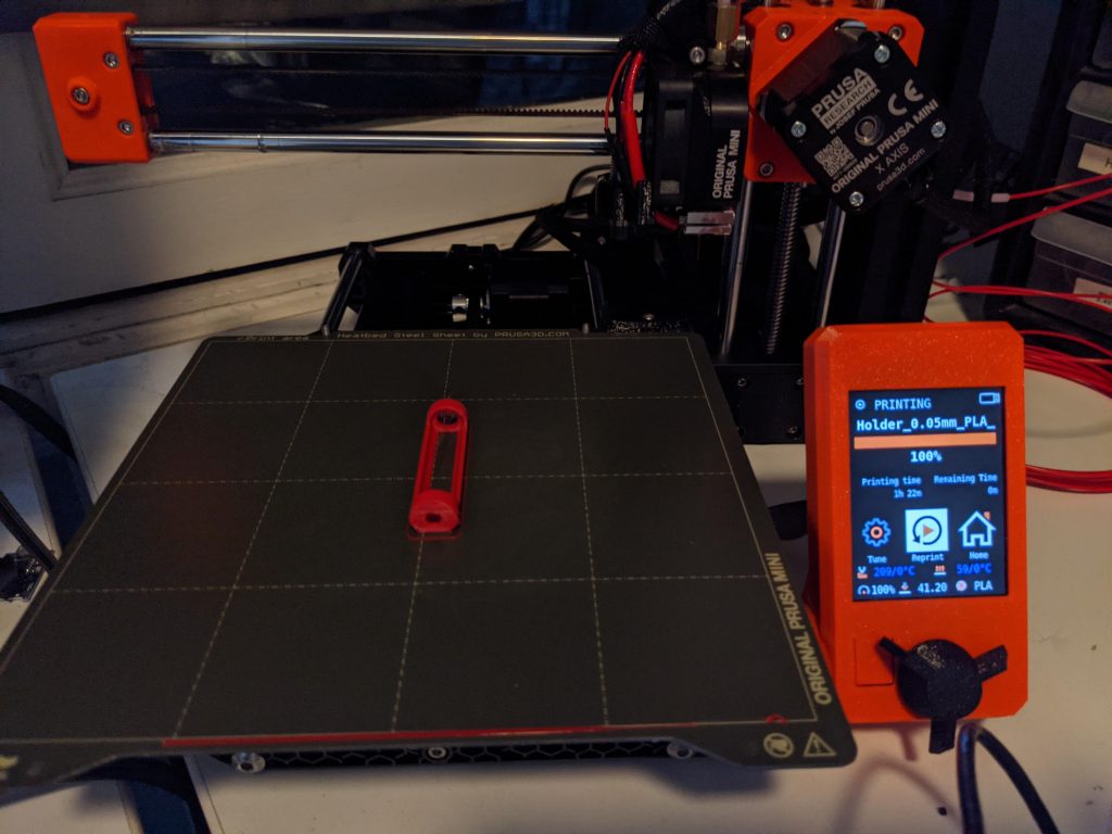
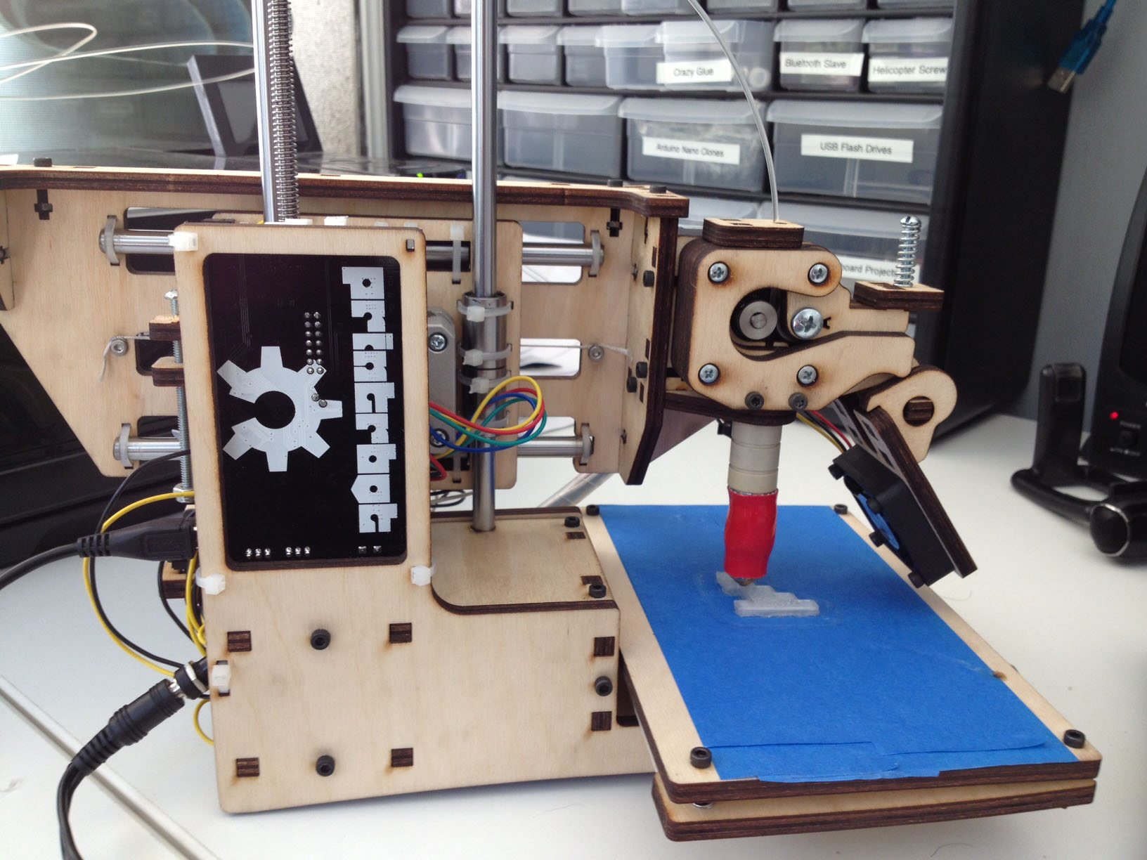
After a long period without a working 3D printer I just got a Prusa MINI+, opening up a wide new range of potential projects. In particular, I finally am able to refine my (laser cut) wearable battery holder. This 3D printed version is significantly improved in sturdiness and ease of use. Also, it’s more accessible to makers since 3D printers are more widespread than laser cutters.
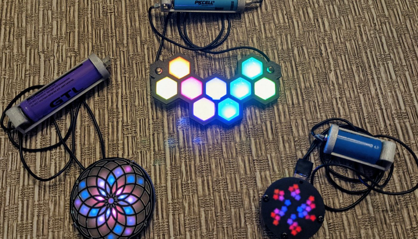
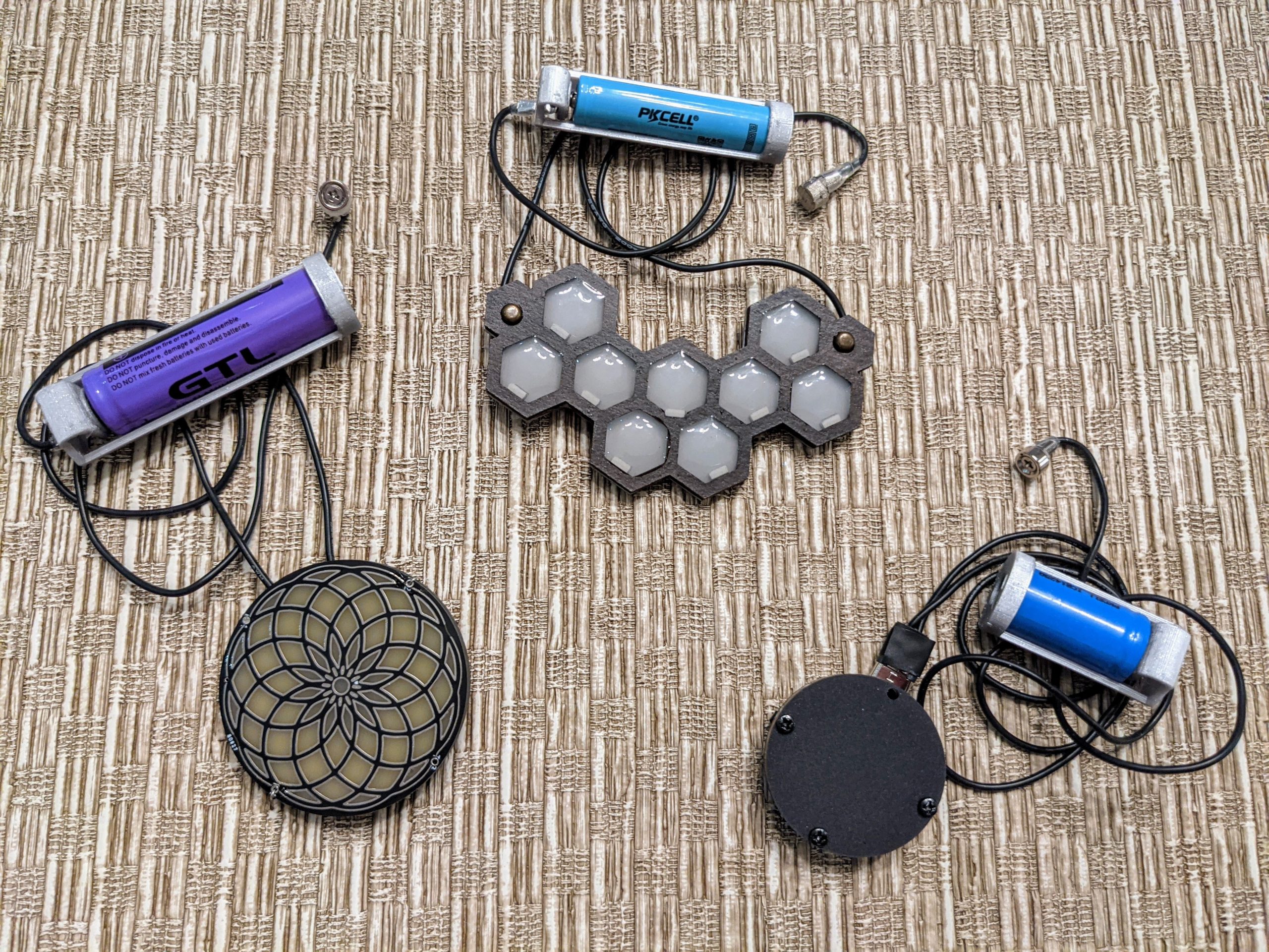
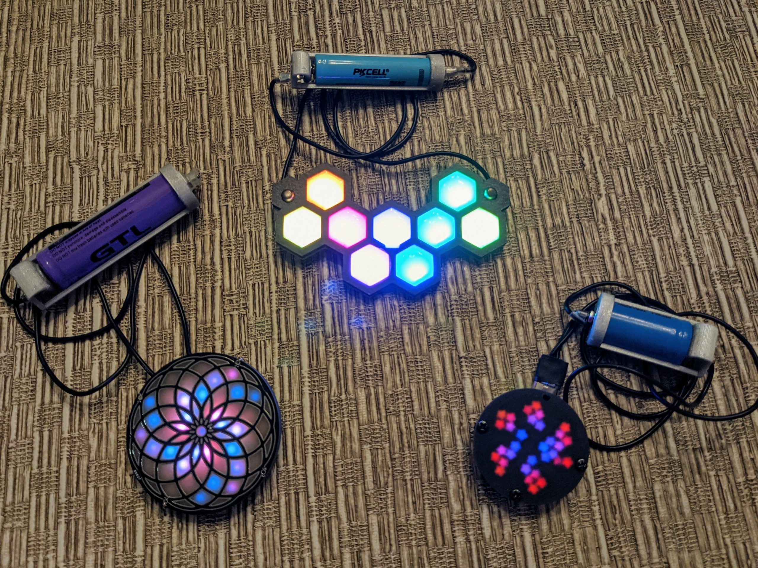
Like the previous version, this battery holder sits behind the neck to both fasten a pendant and complete an electrical power circuit using a magnetic connection. The design is minimal and slim because it doesn’t completely encapsulate the cylindrical Li-Ion batteries it holds. There may be a small risk to wearing an exposed battery this way, but it is significantly safer than wearing an unprotected soft-sided LiPo battery. In addition, the magnetic clasp is extremely quick and simple to remove, which makes it safer should an electrical issue arise.
Design Files
The holder design utilizes a bent arc of PLA to maintain compression between contacts and battery. The electrical contacts consist of flathead or machine screws (depending on the desired spacing). There are STL files to print this holder for 10440, 14250 and 14500 battery sizes.
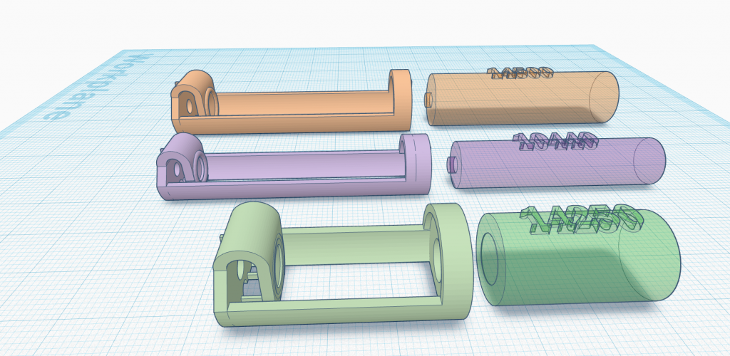
All CAD was done with Tinkercad and the designs are available here: https://www.tinkercad.com/things/kGwEvbR91oy-wearable-battery-holder-public
The STL design files for 3D printing are available on the Prusa site: https://www.prusaprinters.org/prints/91635-wearable-li-ion-battery-holders
Materials
Components
- PLA (or similar) filament
- 26 AWG stranded wire (in whatever color you want for the necklace – I like to use black)
- Small diameter (4-6 mm approx) shrink tube
- Short (about 5mm or 6mm long) screw and nut to form the positive battery terminal. They must be made from conductive metal. The design uses flathead screws, but if you find that you need a tighter hold on the battery, try swapping in a machine screw instead. If you are building the 10440 holder, use an M2 sized screw and nut, otherwise use an M3 sized screw and nut.
- I’ll describe two methods for attaching the wire to the positive battery terminal. One uses a crimp ring and the other uses soldering so you’ll need one of the two items below:
- Magnetic connector materials for the negative battery terminal. I’ll describe two possible construction methods, so you’ll need materials for only one of the methods below:
- Method 1:
- 1x countersunk or ring neodymium magnet, 1/4″ in diameter e.g. this one or these ones or these ones
- 1x short (6mm – 8mm) M2 flathead screw
- 1x M2 nut
- Method 2:
- 2 x 1/4″ (6mm) neodymium magnets
- Short length narrow conductive fabric tape (e.g. this one )
- Method 1:
Tools
- 3D printer or 3D printing service
- Screwdriver(s)
- Crimp tool or pliers (if you use a crimp ring)
- Flush cutter or craft knife
- Wire stripper
- Fine-tip tweezers and painters tape (optional) help hold everything in place during assembly
Construction and Assembly
Printing Notes
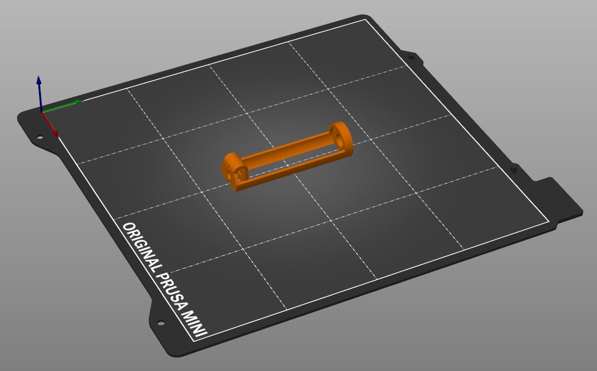
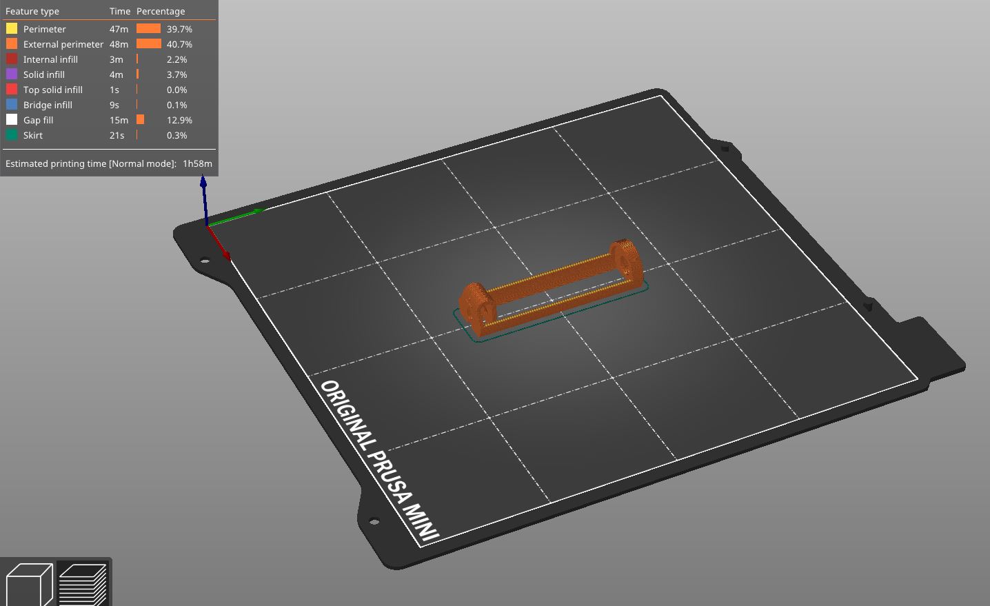
Links to STL and gcode files are in the Design Files section above. Print the model corresponding to the selected battery size. Each design has two small structures that hold the bottom of the PLA arc in place while printing, because otherwise it can get knocked over easily in the early print stages. The model has a small footprint so I used a thin layer of (regular) glue stick on the Prusa print bed to help adhesion, which worked quite well.
I tried printing the model with a brim to see if that secured it to the bed any better, but the structure is rather delicate, and it was very hard to remove the brim without damaging the holder itself. Glue stick was sufficient to keep the holder in place during the print, and I would recommend printing without a brim.
Post-Print Processing
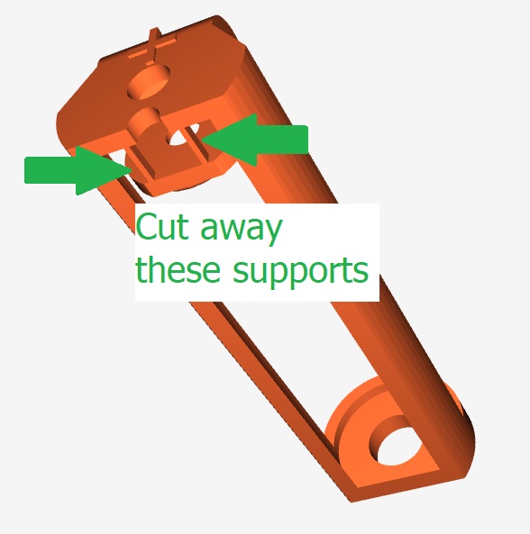
There are two small support structures between the flexible arc and the positive battery terminal, which must be cut with flush cutters or an craft knife before it can be assembled and used. The image above shows their position.
Assembly
Cut two equal lengths of 26 AWG stranded wire. They function both to hold the pendant (or other wearable) and to carry power to the electronics. If you ‘re not sure of the right length, go a bit too long rather than too short, because you can always trim them down later.
Construct the Positive Terminal
We’ll create the positive terminal from an M3 6mm (approx) flathead screw/nut pair secured to the stripped end of one wire. If you need stronger contact between the screw and battery, then you can switch to a machine screw from a flathead screw.
Because you’re working with small parts in a small space, it is a challenge to align the nut against the hole for the screw. Pointy tweezers and painter’s tape can help to hold the elements in the right place.
There are two different ways to construct the positive terminal shown below.
Positive Terminal Method 1: Ring Terminal (No Soldering)
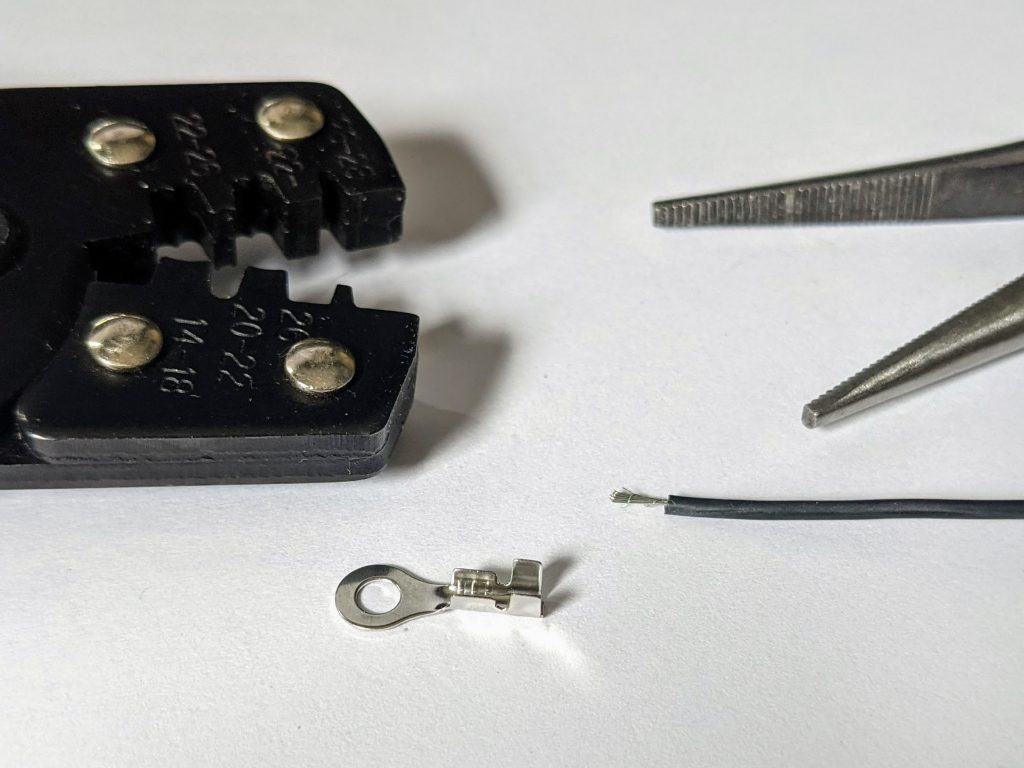
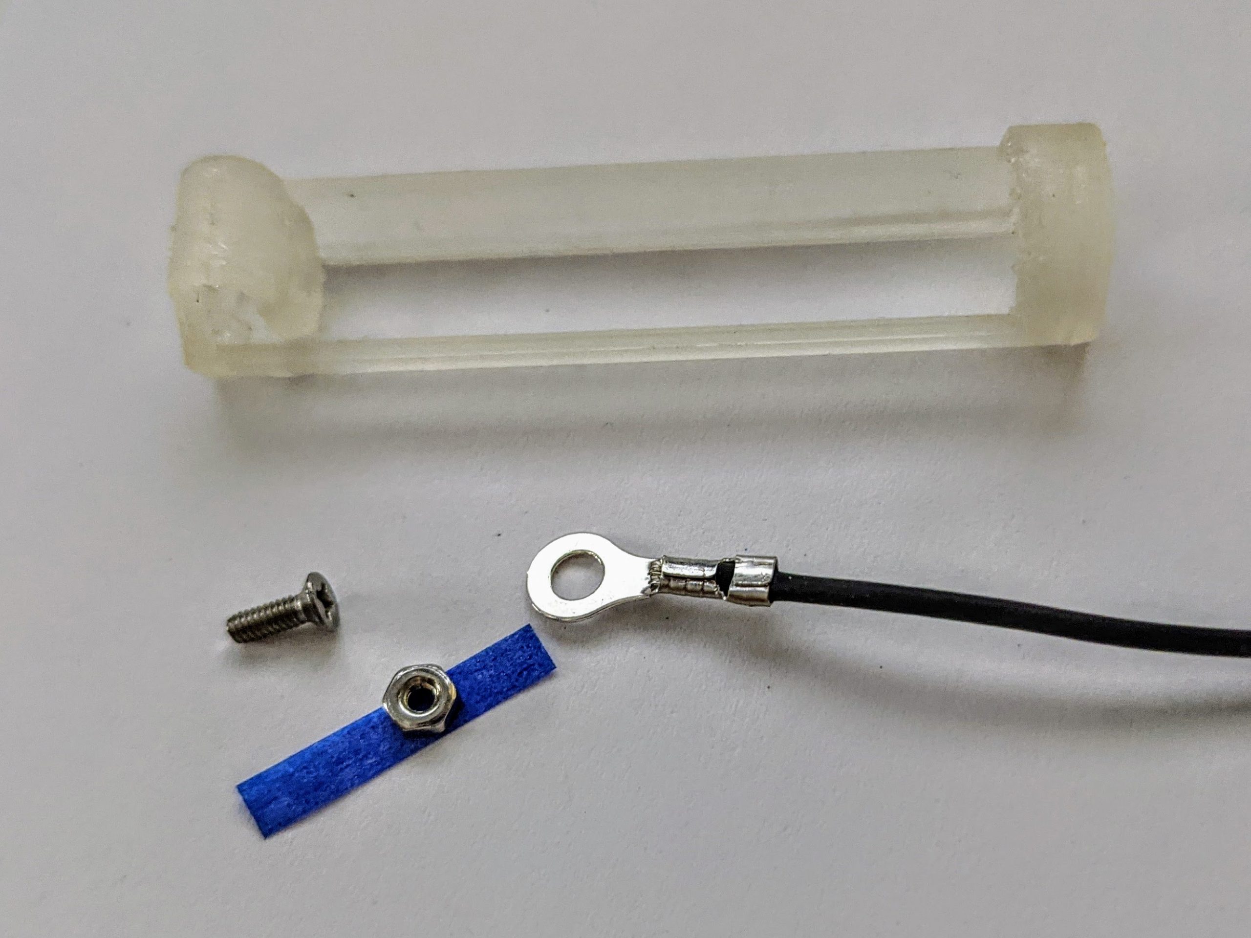
Use an M3 crimp ring with prongs that fold to secure the wire. 
Either a crimp tool or pliers work well for this task.
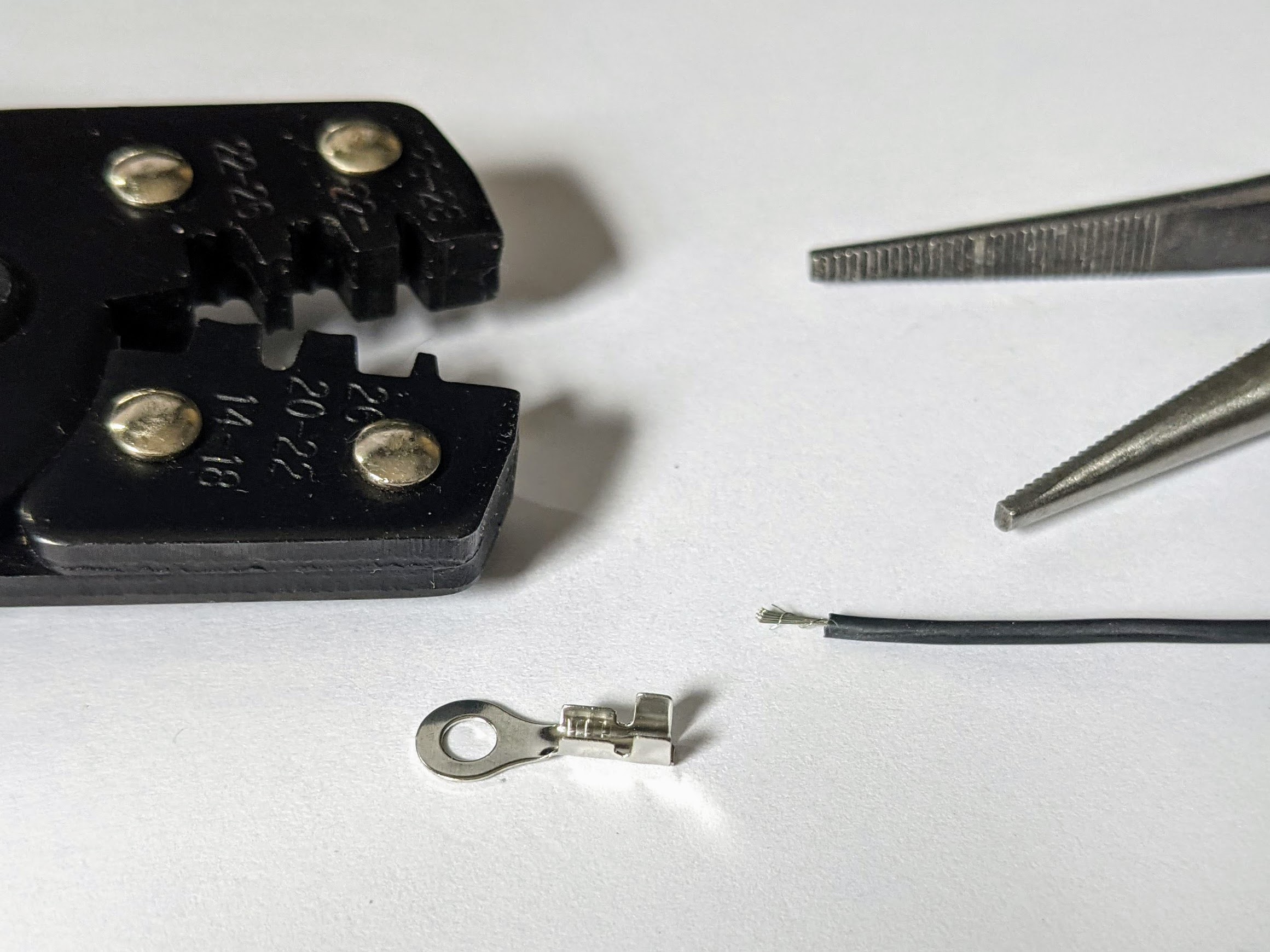
Use your crimp tool or pliers to crimp one end of the 26 AWG stranded wire into the ring terminal as shown above.
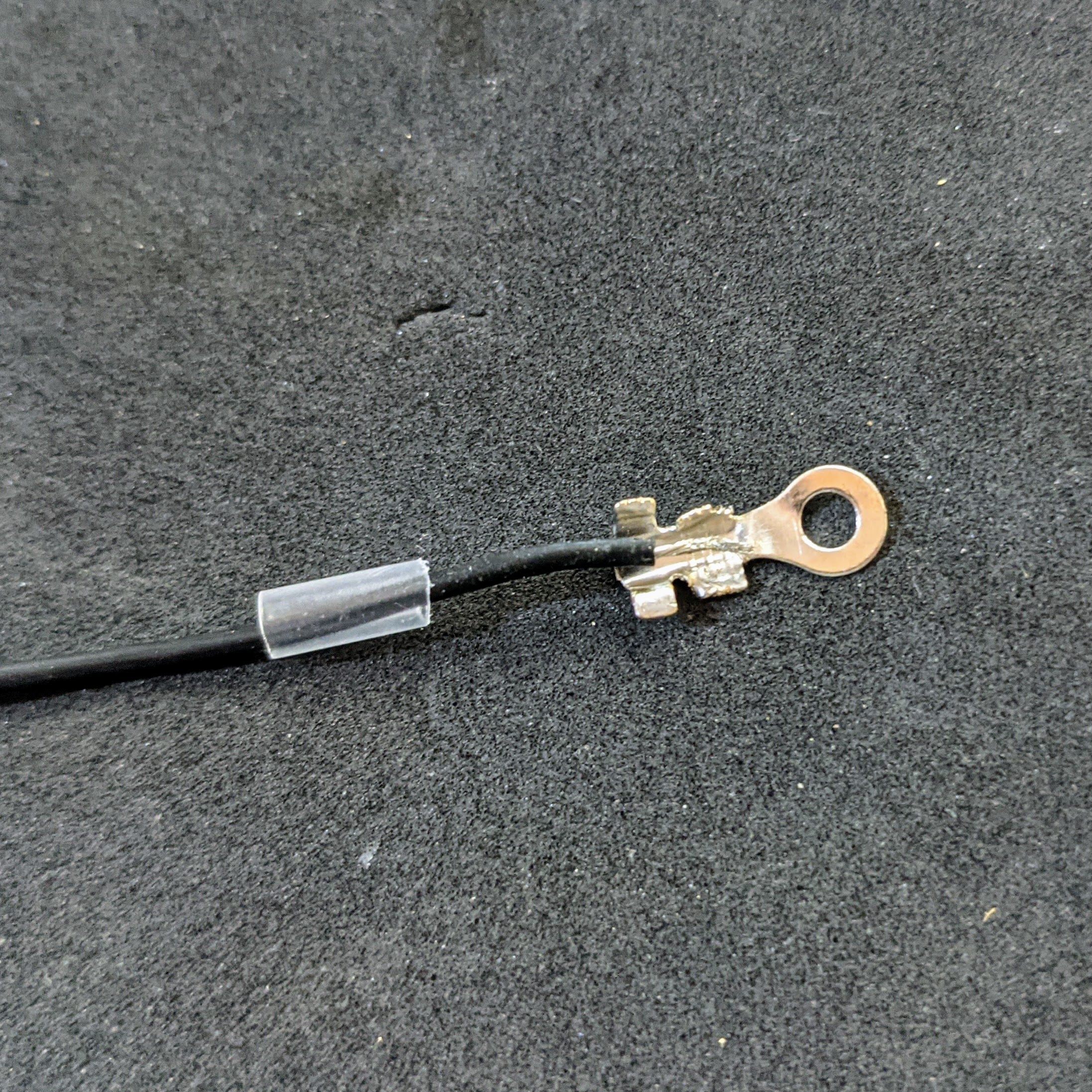
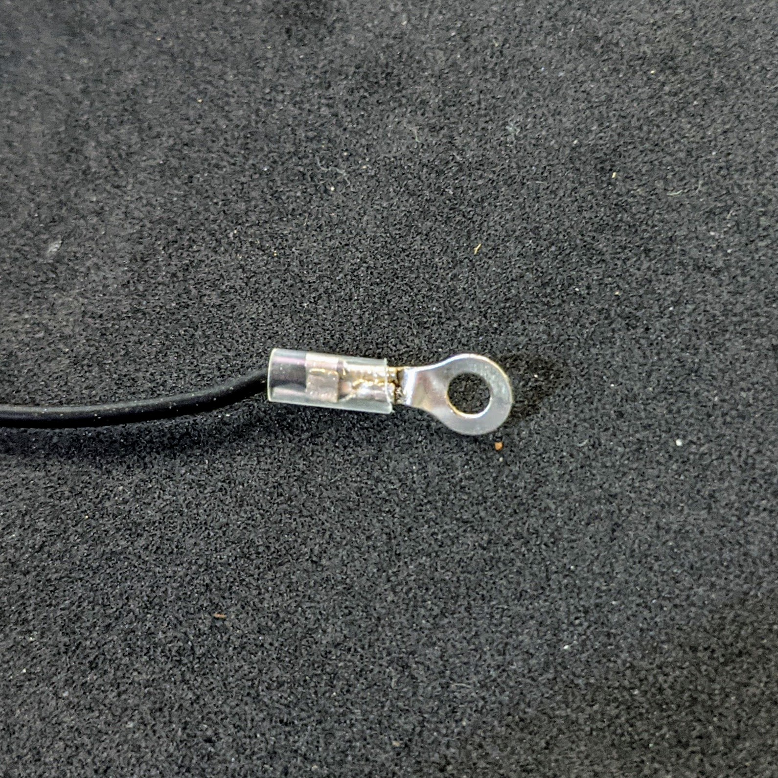
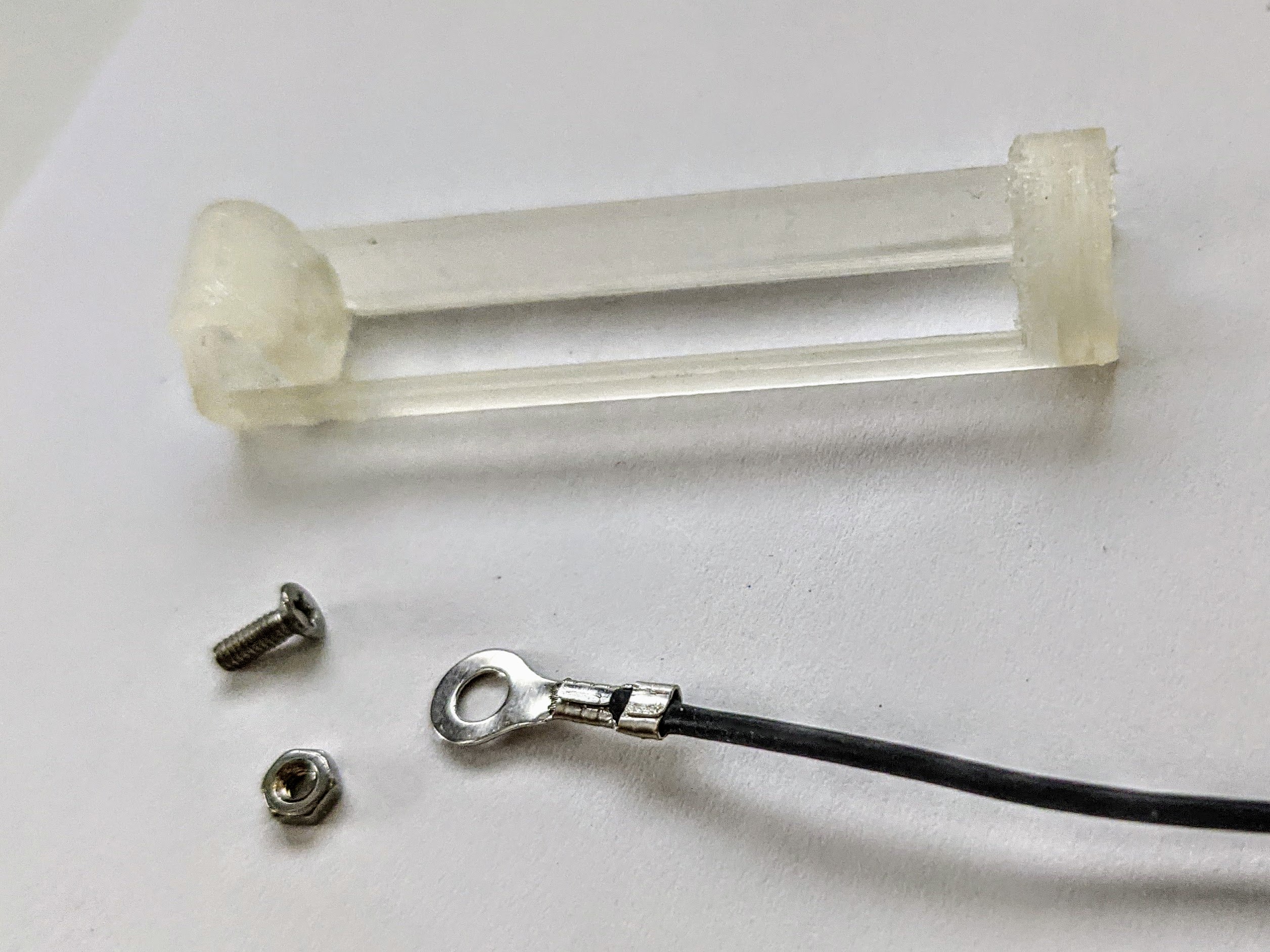
I forgot to do this when taking most of the pictures, but it’s a good idea to place a piece of shrink tube over the shaft of the crimp ring and wire. This helps with both strain relief and insulation.
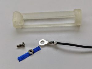
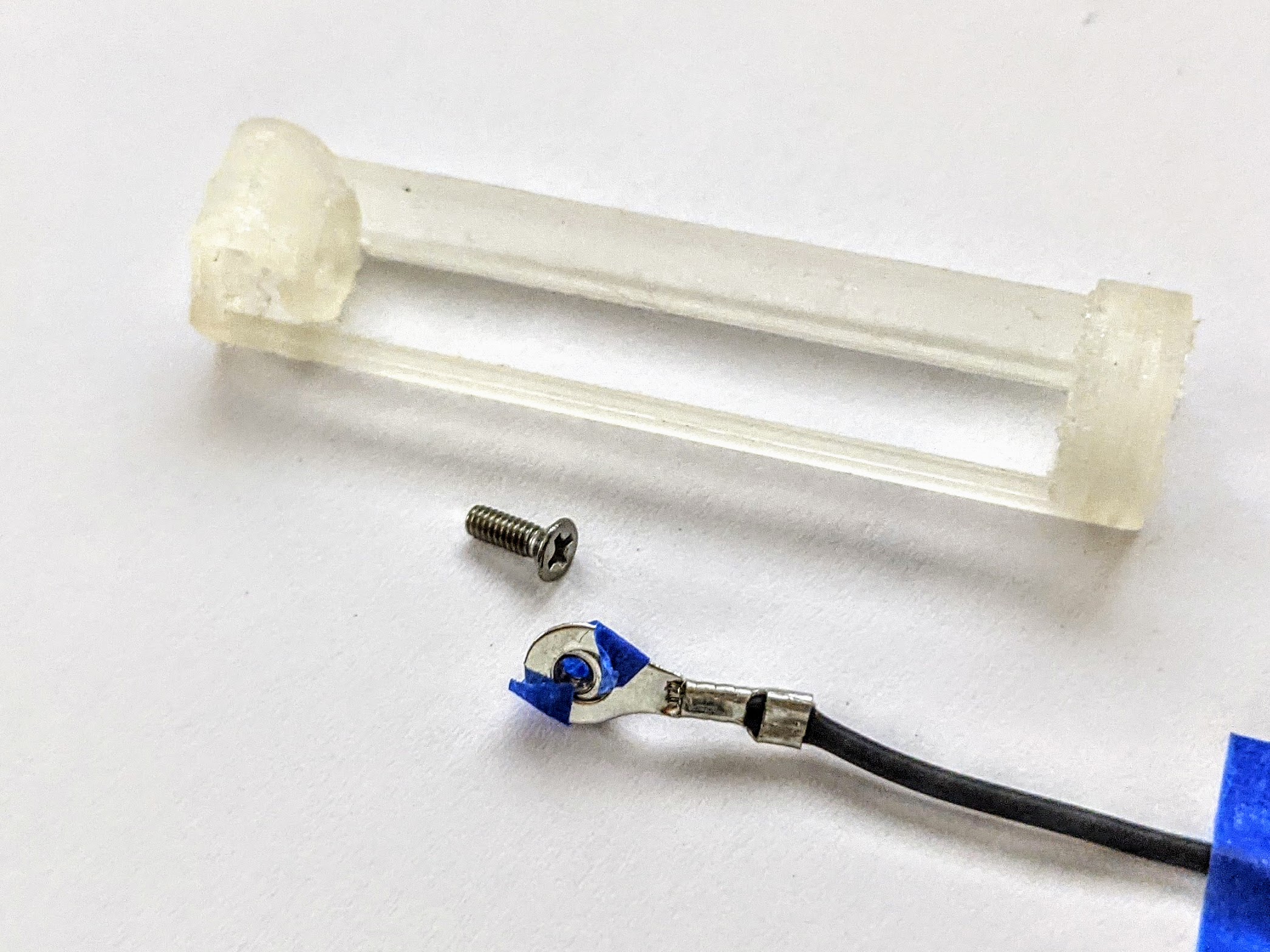
A very small piece of tape attaches the nut to the crimp ring. 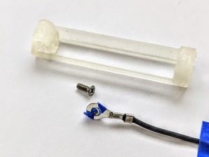
Be sure that the tape doesn’t cover the crimp ring hole. 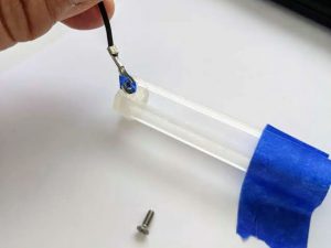
Tape the holder upside down before inserting the nut and ring terminal into the underside of the PLA arc. Narrow tweezers will help to insert it so that the holes in the crimp ring and battery holder line up. 
A small pliers is helpful in holding the screw in place for tightening, and a long screwdriver makes accessing the screw easier

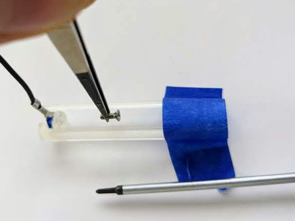
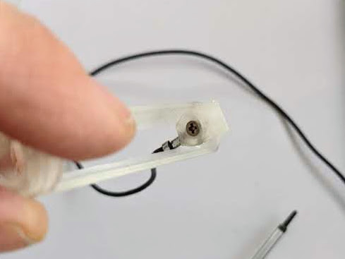
Turn the battery holder over so that you can access the underside of the PLA arc. It will help to tape it in place with painters tape. The arc is the positive battery terminal. You will need to pass the small (approx 6mm) flathead screw from the inside of the holder, through the hole in the PLA of the arc, through the crimp ring, then screw it into the battery holder.
The hardest part is lining up the holes in the PLA, crimp ring, and nut. The technique I found to work best for me was to use a tiny piece of tape to stick the nut to the crimp ring, then use tweezers to insert the crimp ring into the arc. Once in place, hold the screw with tweezers, while fastening it with a long-shafted screwdriver. The four images above, show this process. It may take a few attempts to make it work, but keep trying. It is possible.
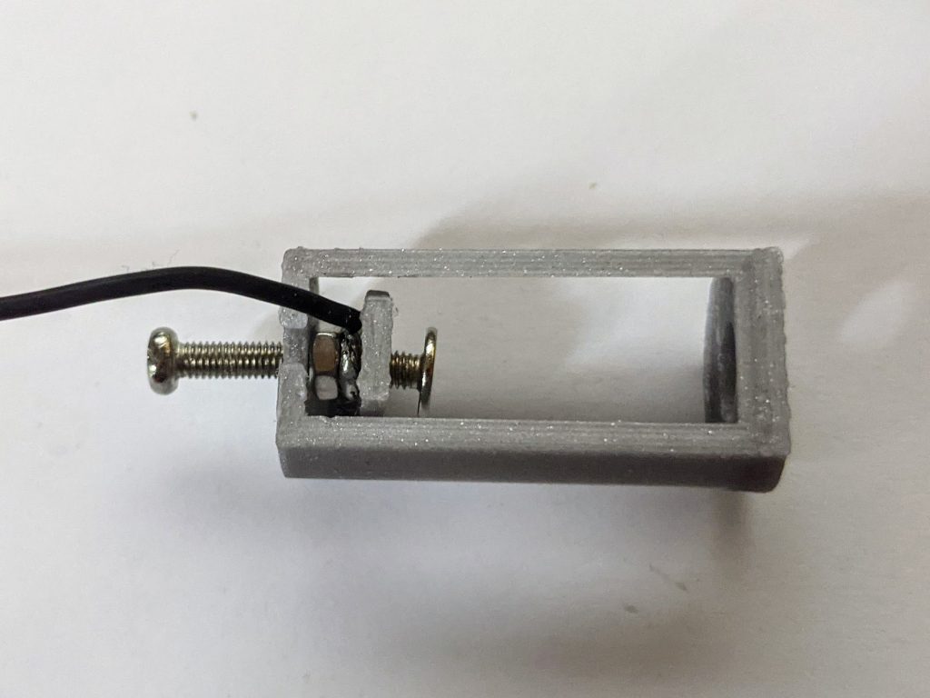
An additional long screw on the opposite side of the nut can help to hold it in the right place when tightening the screw from inside the holder
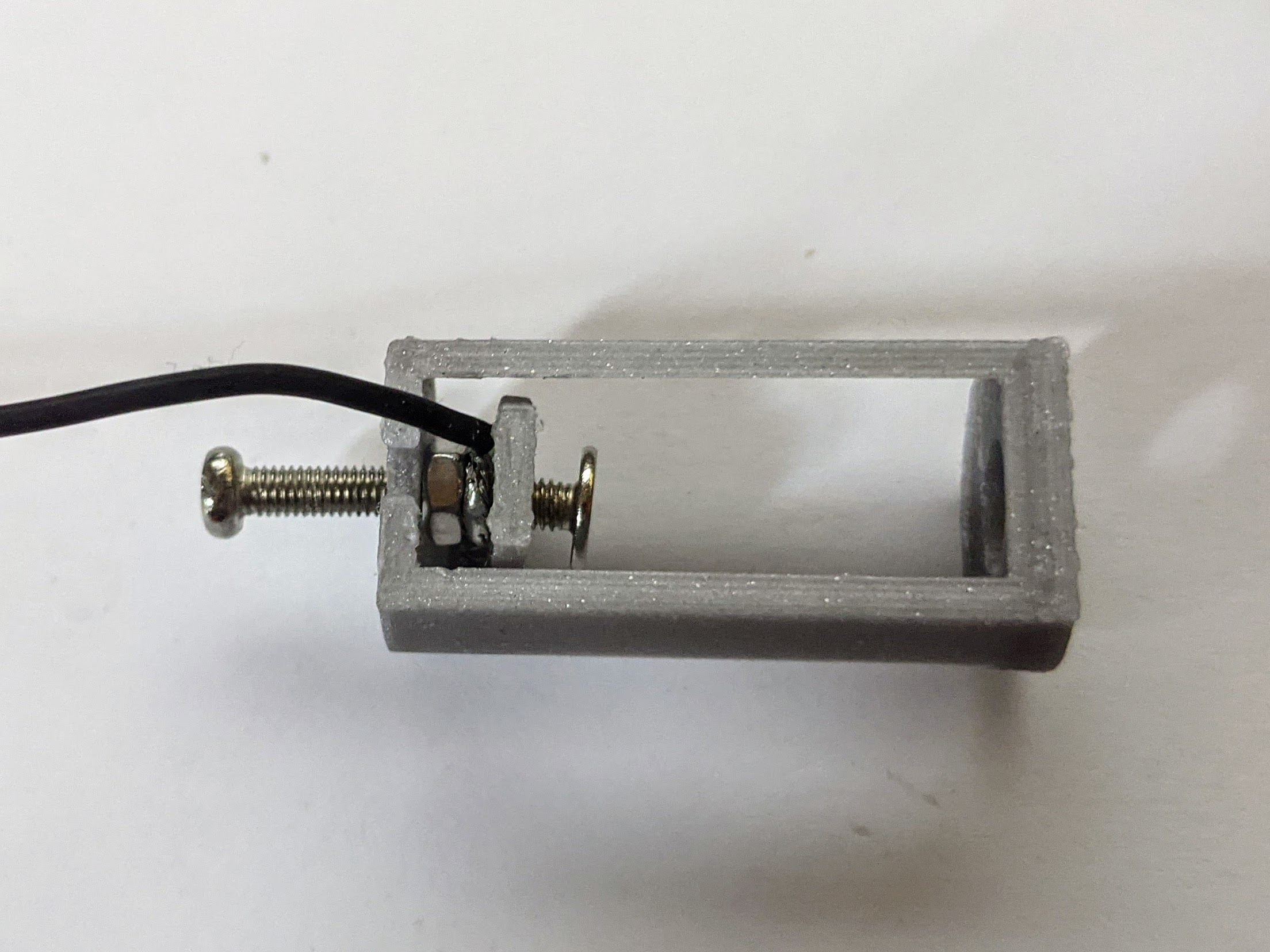
Another technique to try if the tape isn’t working for you is shown in the image above. Place only the nut into the arc, and insert a longer screw from the outside of the holder into the nut. Twist enough to get the screw about halfway through the nut. You can then use this long screw to hold the nut in place while you insert the wire and then insert and tighten the contact screw from the inside.
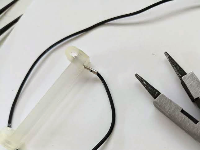
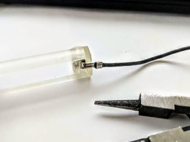
Positive Terminal Method 2: Solder a Loop
This technique for securing the positive terminal isn’t as sturdy as method 1, but does not require any hardware beyond the screw and nut.
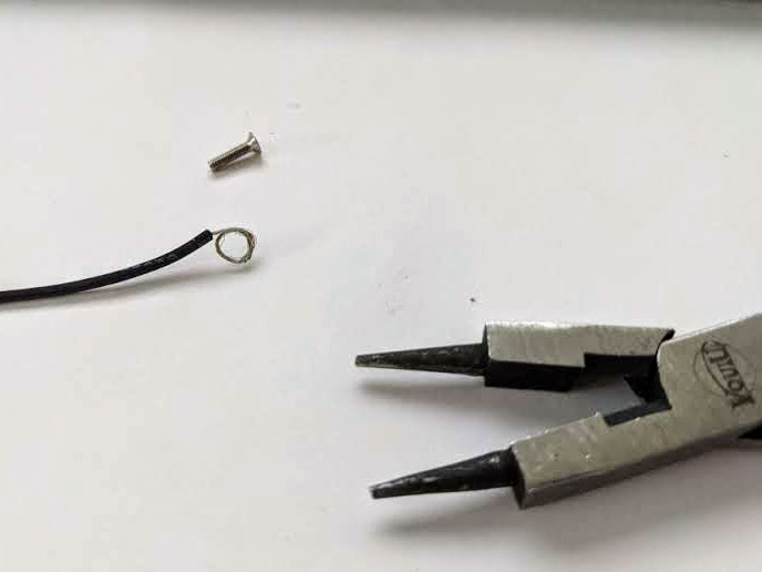
Simply use pliers as shown above, to bend a length of stripped wire into a ring, and, using a small amount of solder, secure it into a ring shape before following the steps listed in method number one. Before soldering, be sure there is enough room in the loop to slide the screw through its center.
Construct the Negative Terminal
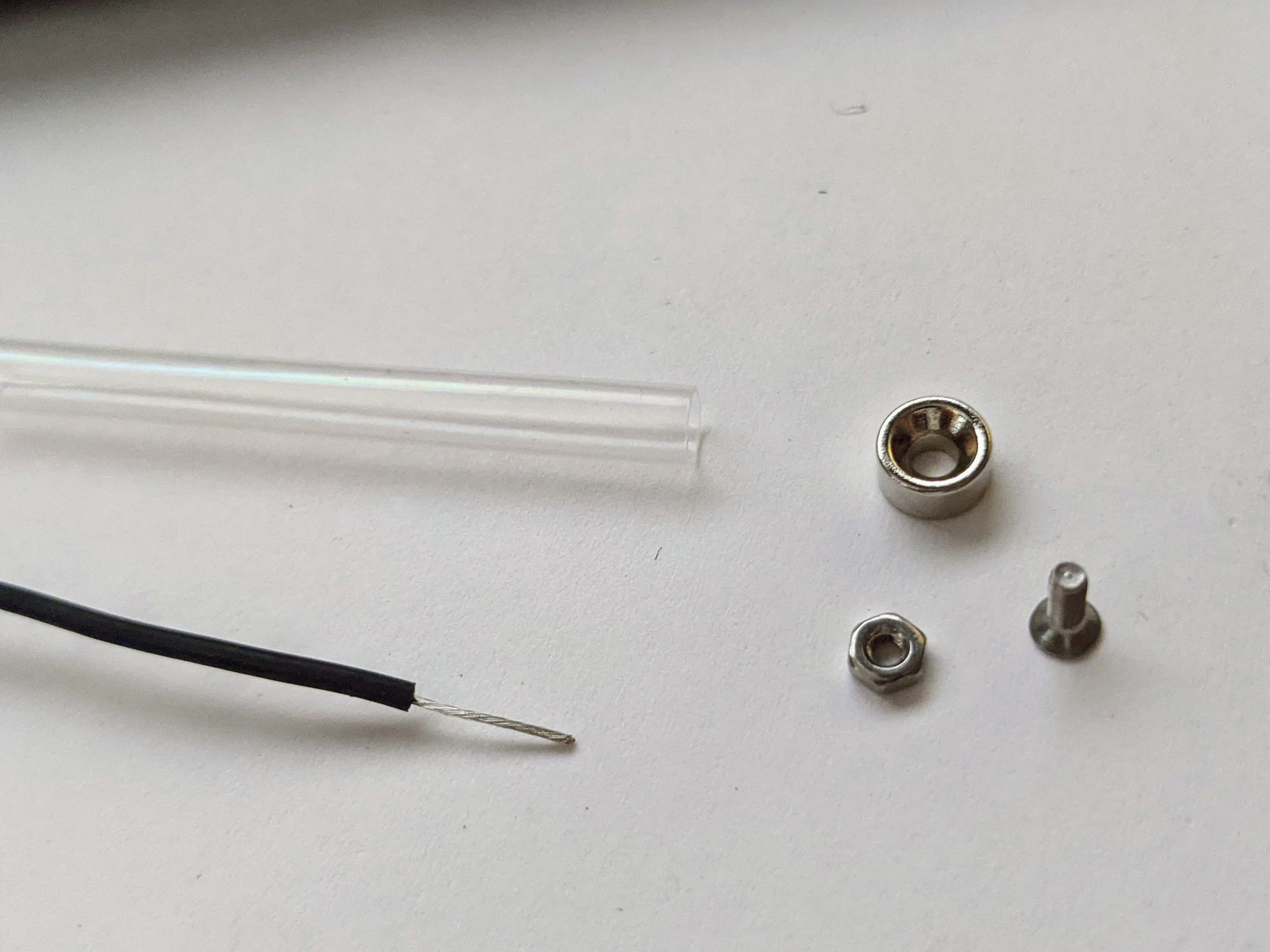
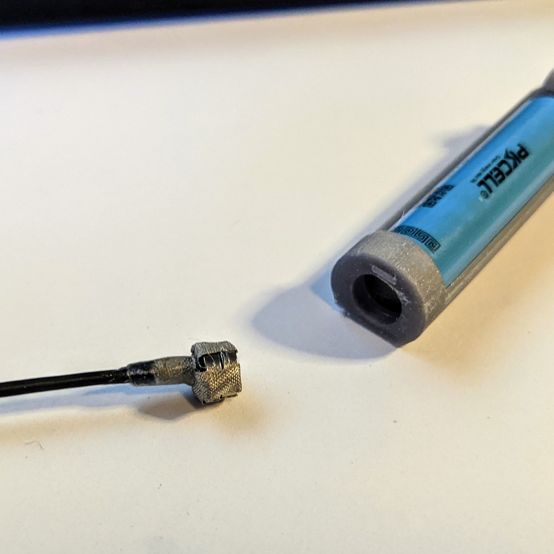
The negative connector consists of the other length of stranded wire attached to small cylindrical/disk neodymium magnets on one end. The magnetic end slides into the large hole in the holder and adheres to the flat negative battery terminal. The hole in the negative battery holder terminal is purposely deep to prevent sideways torque from pulling the magnet away from the battery.
As before there are two different methods for constructing this terminal. The first method is sturdier, and recommended, but requires finding a 1/4″ diameter countersunk disk magnet which may be difficult for some. Sources for small countersunk magnets are listed in the components section of this tutorial.
Negative Contact Method 1: Countersunk Magnet with Screw/Nut
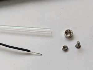
The countersunk magnet attaches to the wire with an M2 flathead screw and nut 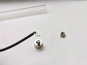
Loop the stripped wire end and slip it over the end of the screw on the flat side of the magnet 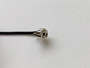
Tighten the screw to secure the wire 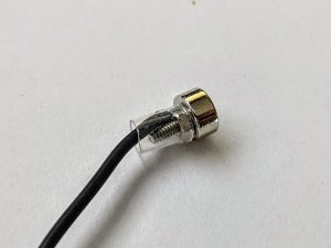
Add a small piece of shrink tube to provide insulation and strain relief
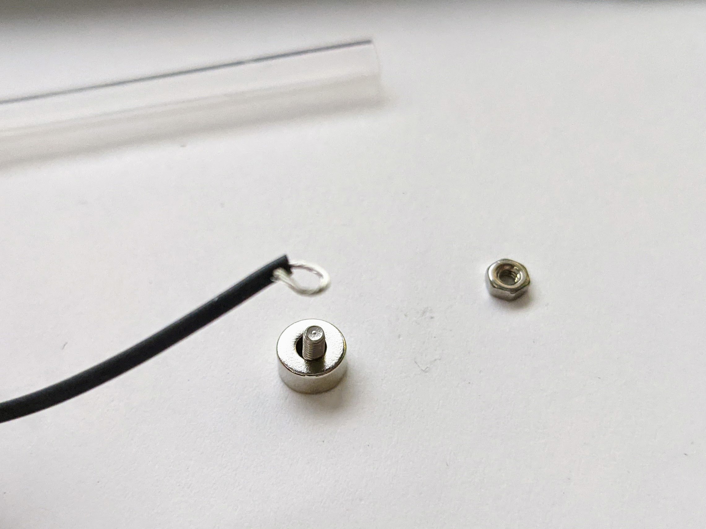
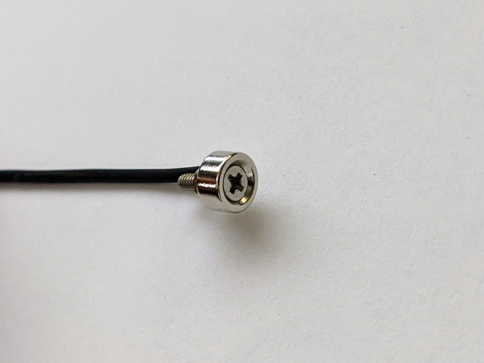
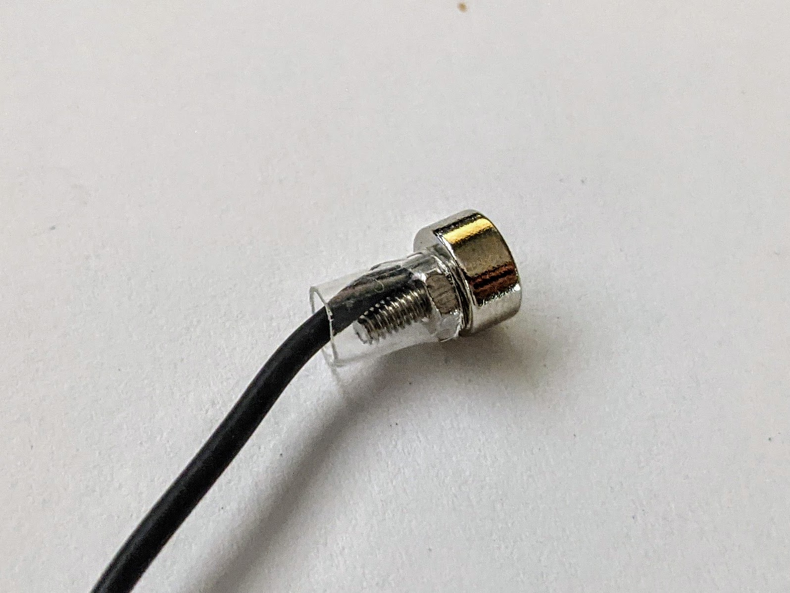
This method is fairly simple to construct. Strip the end of the stranded wire and form a small loop. Place the M2 flathead screw through the countersunk magnet from the recessed side. Slip the wire loop over the end of the screw that extends out the magnet’s flat side. Fasten the wire to the magnet with the M2 nut. Use shrink tube to hold the wire in place against the screw and to provide strain relief. Don’t place the shrink tube over the magnet itself, or the magnet won’t fit into the hole in the battery holder.
Negative Contact Method 2: Neodymium Disk Magnets with Conductive Tape
You may find it hard to obtain 1/4″ countersunk neodymium magnets. Standard 6mm neodymium disk magnets are easier to obtain, so use this method if that’s what you have. You will need 1/8″ wide conductive fabric tape to hold the wire to the magnets.
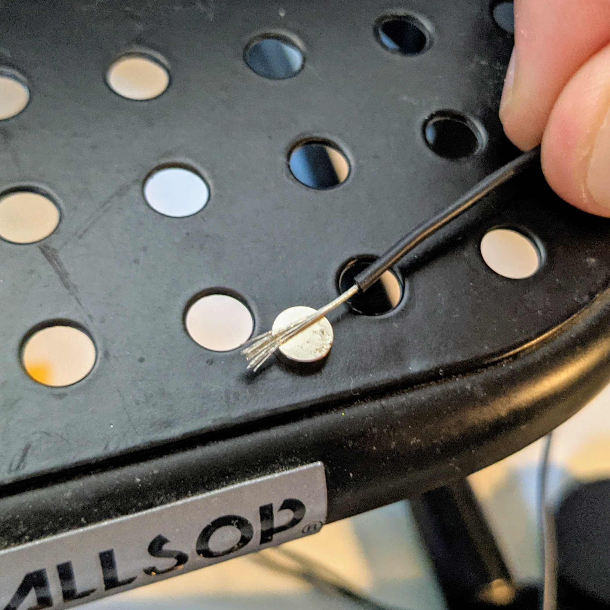
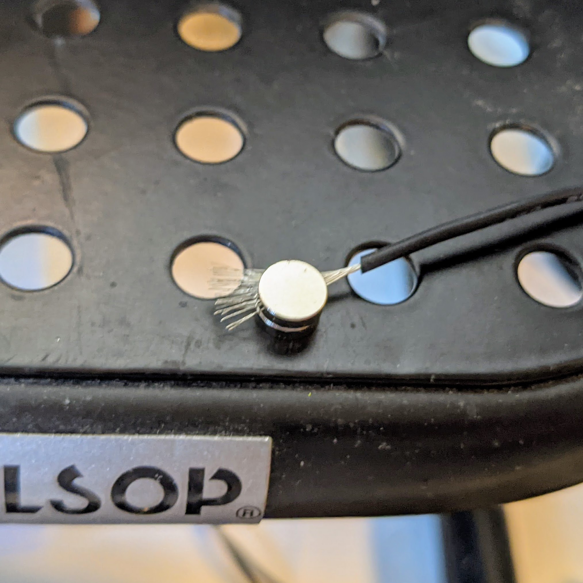
Place the stripped end of the wire between the two small magnets. This is harder than you’d think. The best way to do it is to place one magnet on a large metallic surface, hold the wire over the top, then release the other magnet so it sticks to the first one. Leave a few mm of stripped wire between the wire insulation and the magnets as shown.
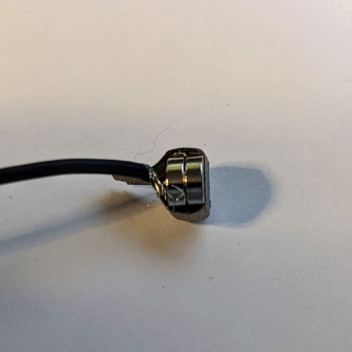
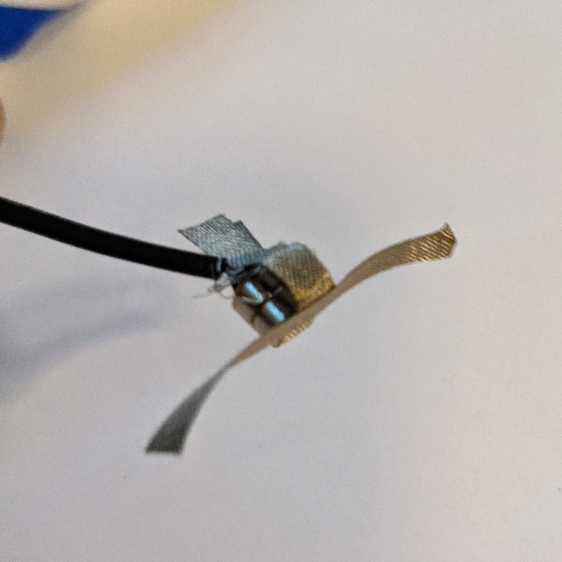
Once the wire is seated between the magnets, wrap a small length of conductive tape around the two magnets and wire. Bring the ends of the tape up and together so they meet over the flat side of the magnet assembly where the insulated wire is. The tape ends should extend about .5 to 1 cm past the magnets and stick together. It is important that the tape not add too much width to the magnet assembly as there isn’t much clearance in the holder. Smooth the tape to ensure it lies as flat as possible against the magnet assembly
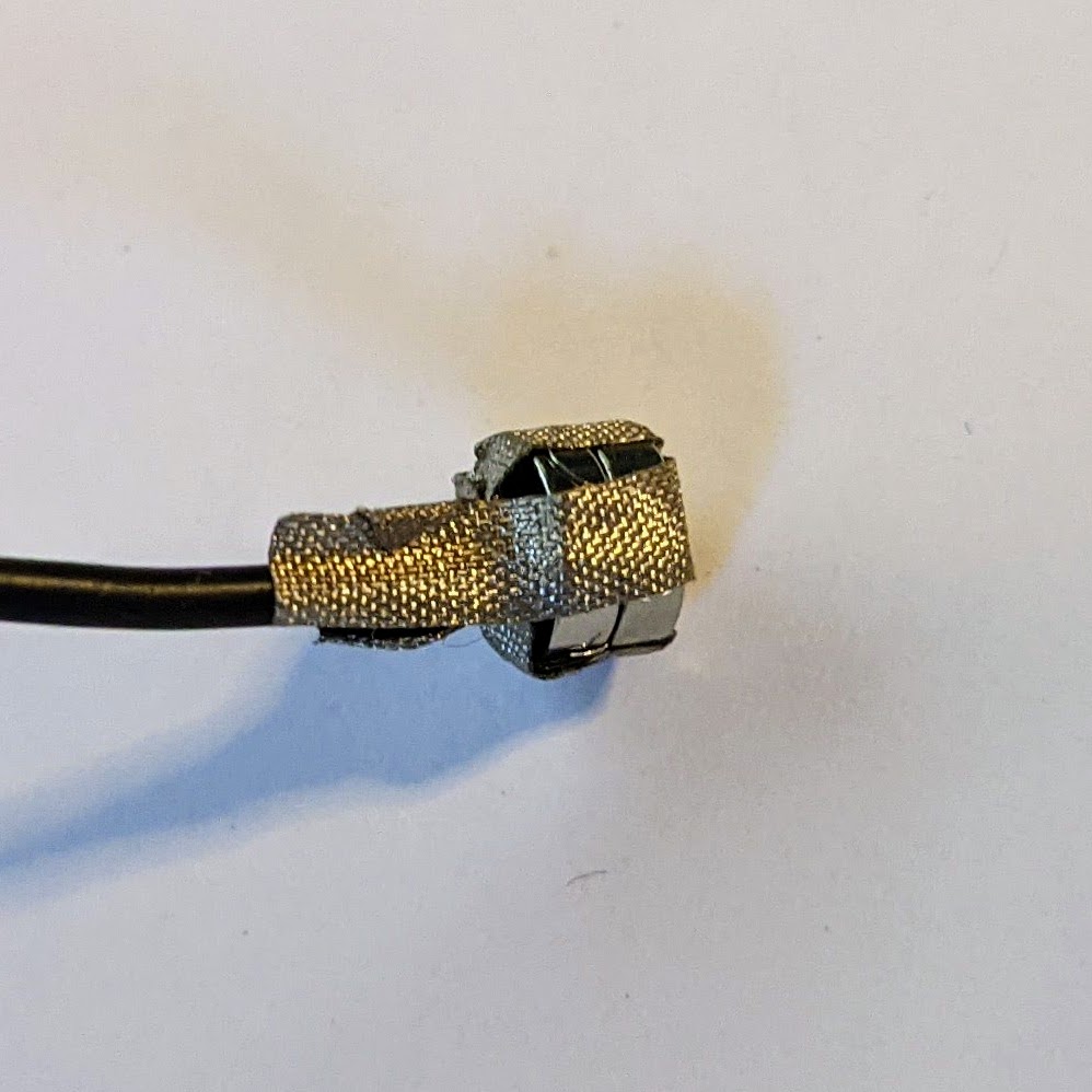
Once the first piece of tape is in place, add a second piece at right angles to the first as shown, and stick the tape ends together to encompass the first set of tape ends and the insulated wire.
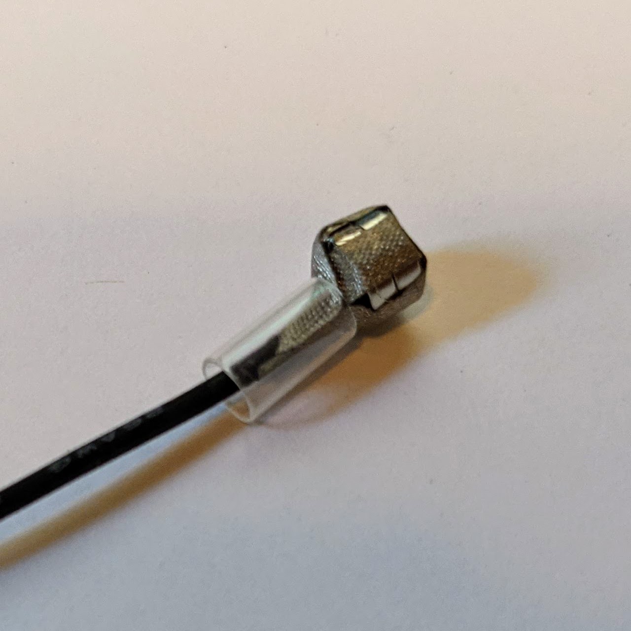
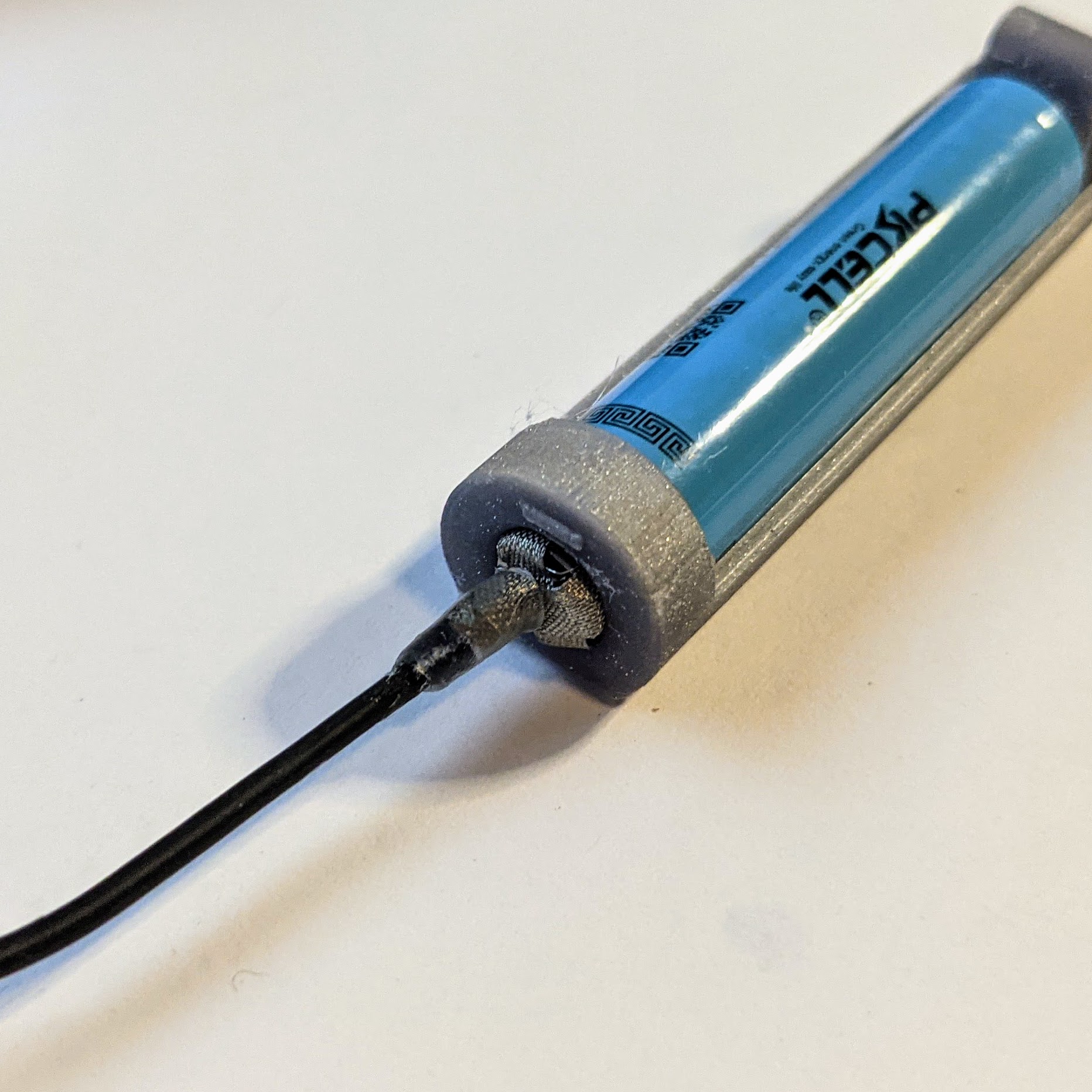
Slip a piece of shrink tube around the end of the wire and the conductive tape that extends past the magnets. Get the tubing as close to the magnets as possible before applying heat to shrink it. If the tape is smooth and flat against the magnets, it will hold them to the wire firmly once the tubing is shrunk. The magnet assembly will slide into the negative terminal of the battery holder as shown above.
Tips for Wiring Electronics
Now that the holder is completed, you’ll have to deicde how you want to attach the electronics. If you solder the free ends of the power wires to a PCB or other electronics assembly, be sure to provide mechanical reinforcement, as solder joints are not structurally strong enough to reliably support a wearable.
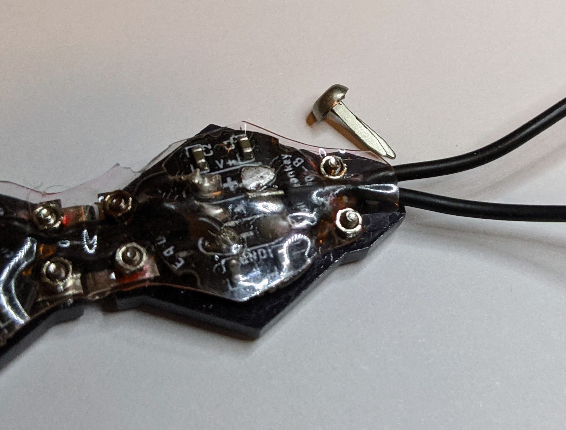
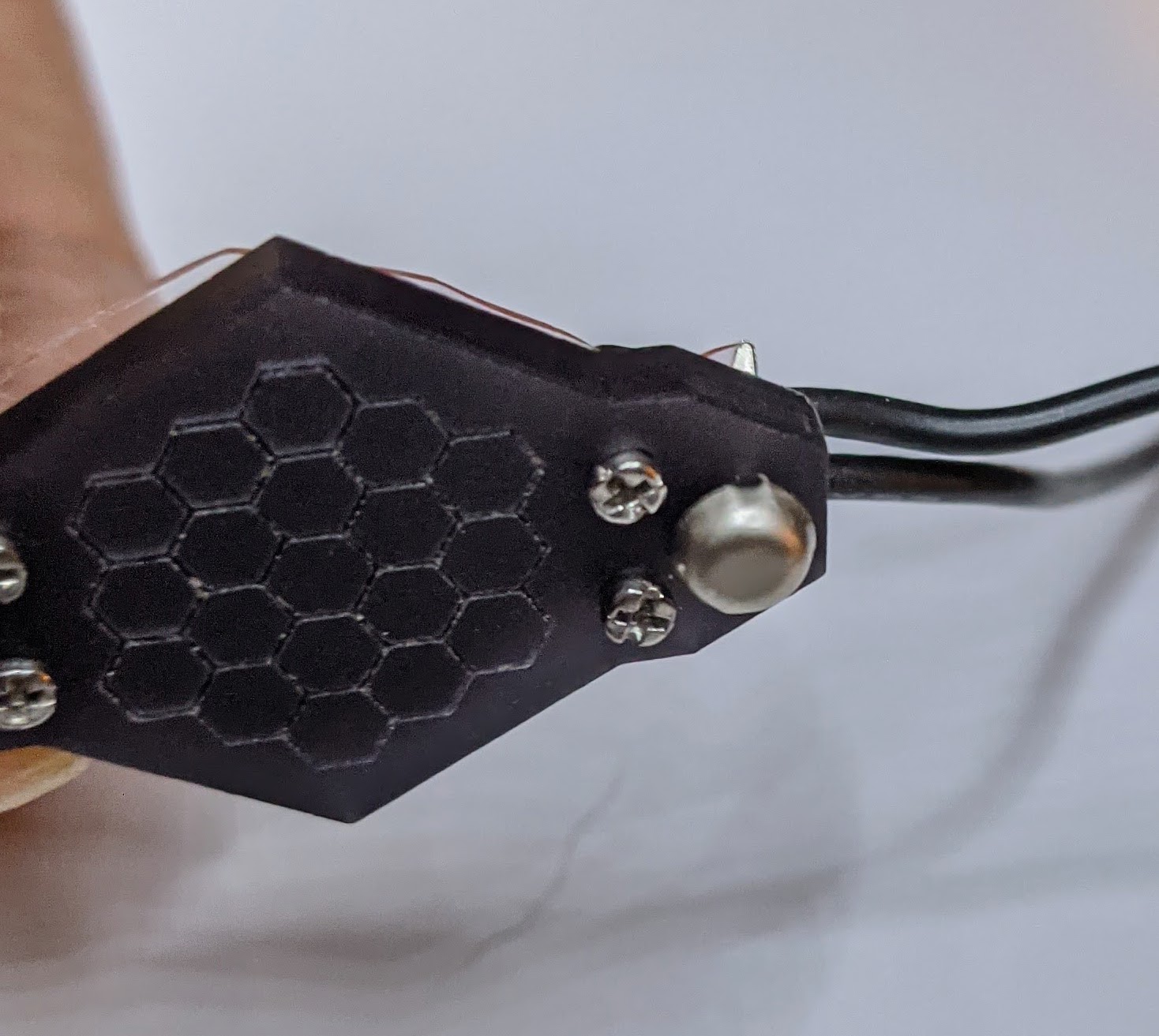
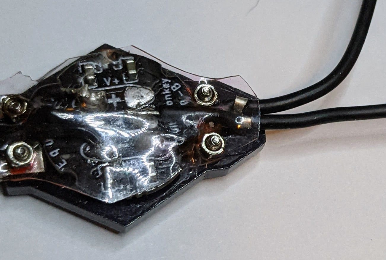
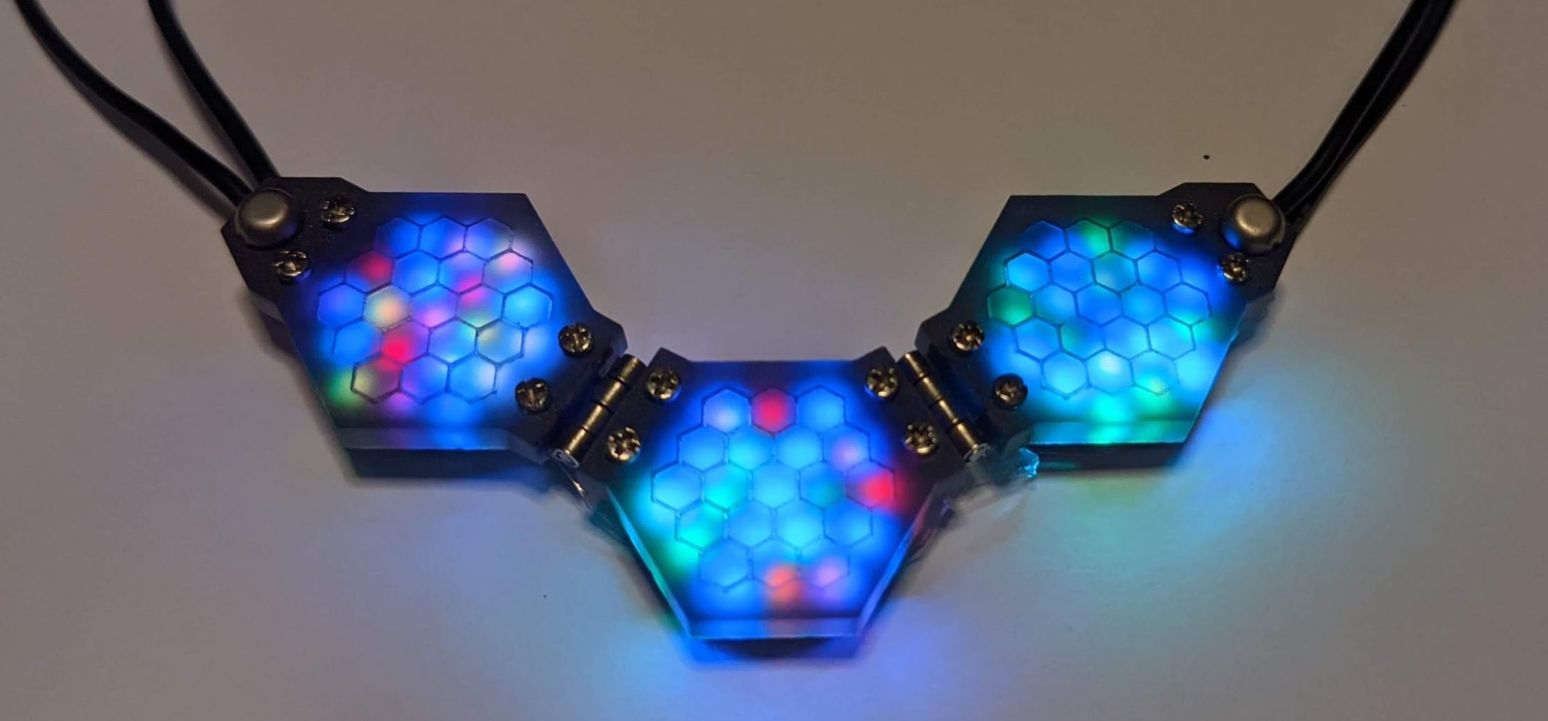
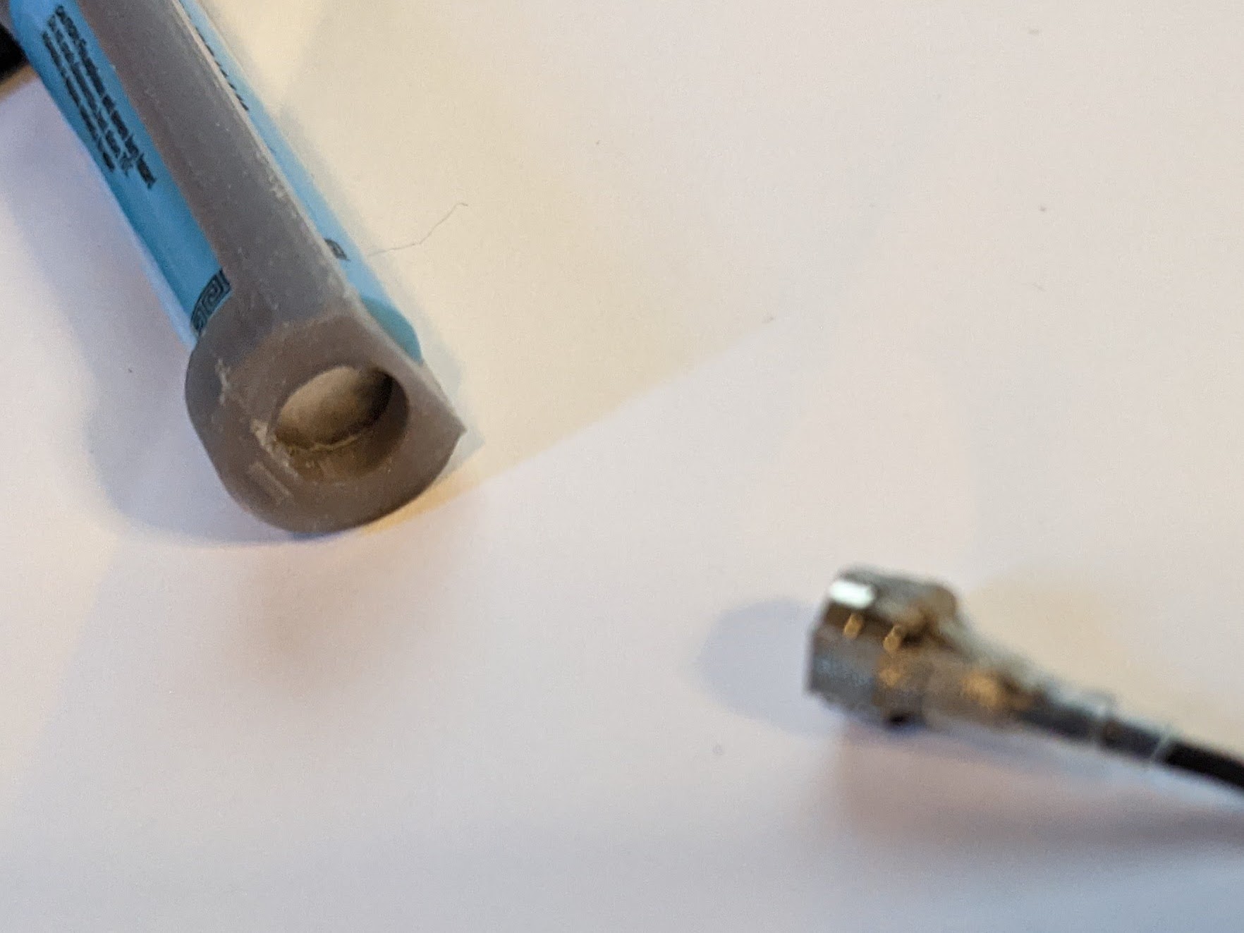
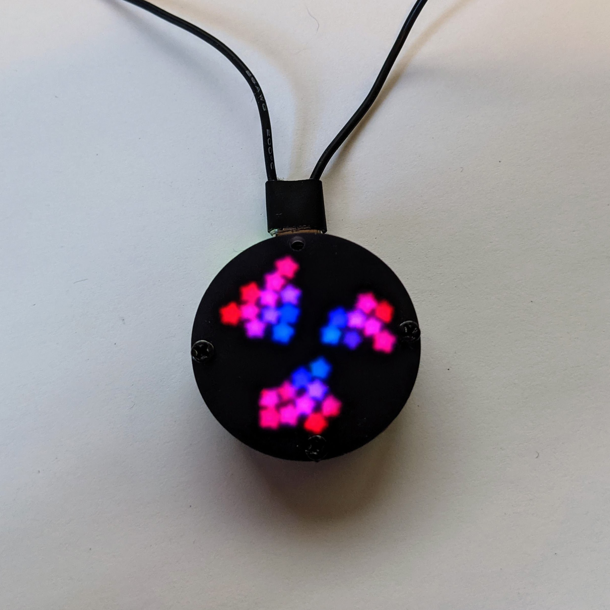
One method I use to provide strain relief to wires in wearables is shown in the illuminated PCB-based pendant above. The wires are soldered directly to the PCB, but tiny metal brads (sold for scrapbooking) run through holes in the PCB and cover layer, and hold the wires against the board to keep stress away from the solder joints.
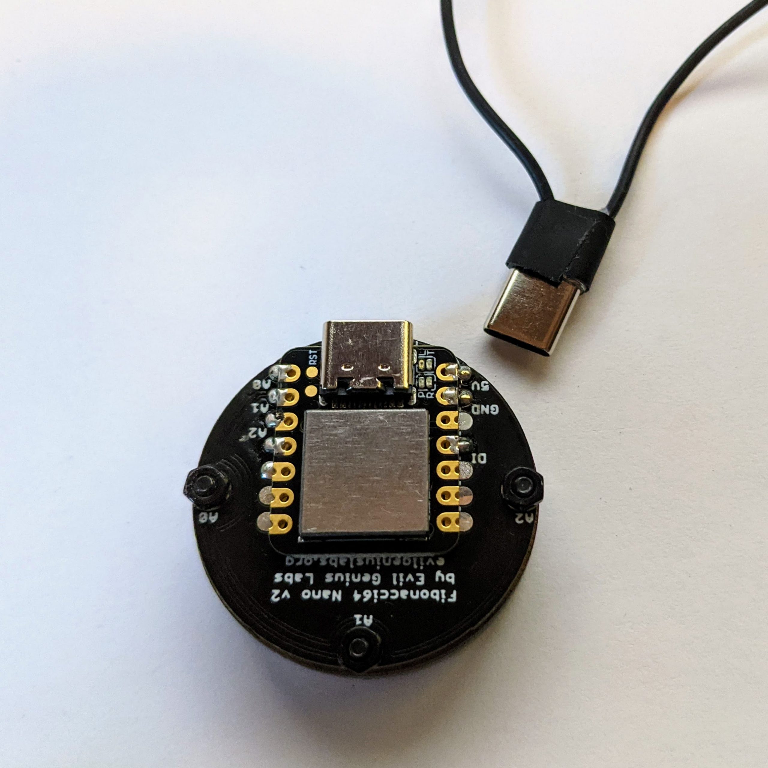
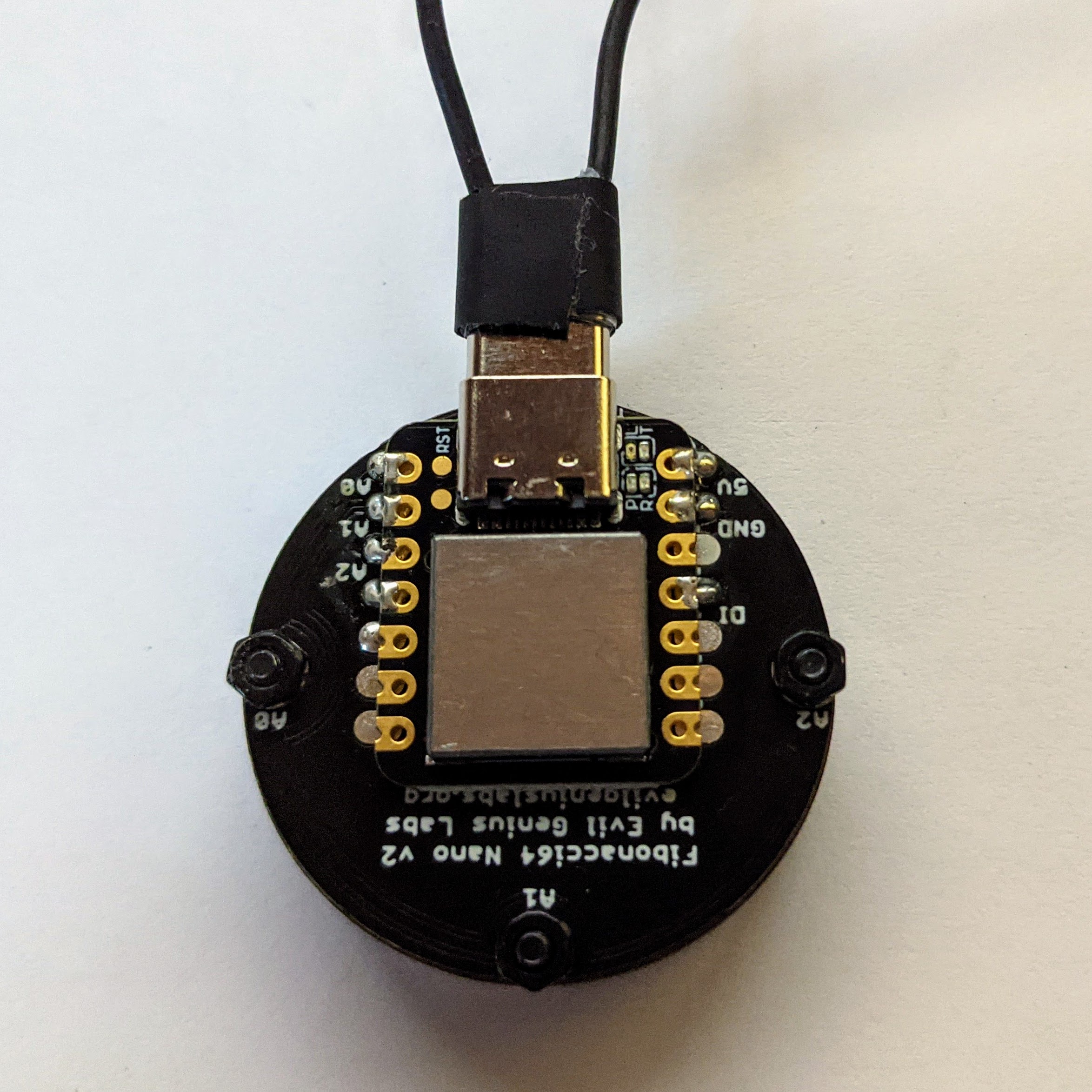
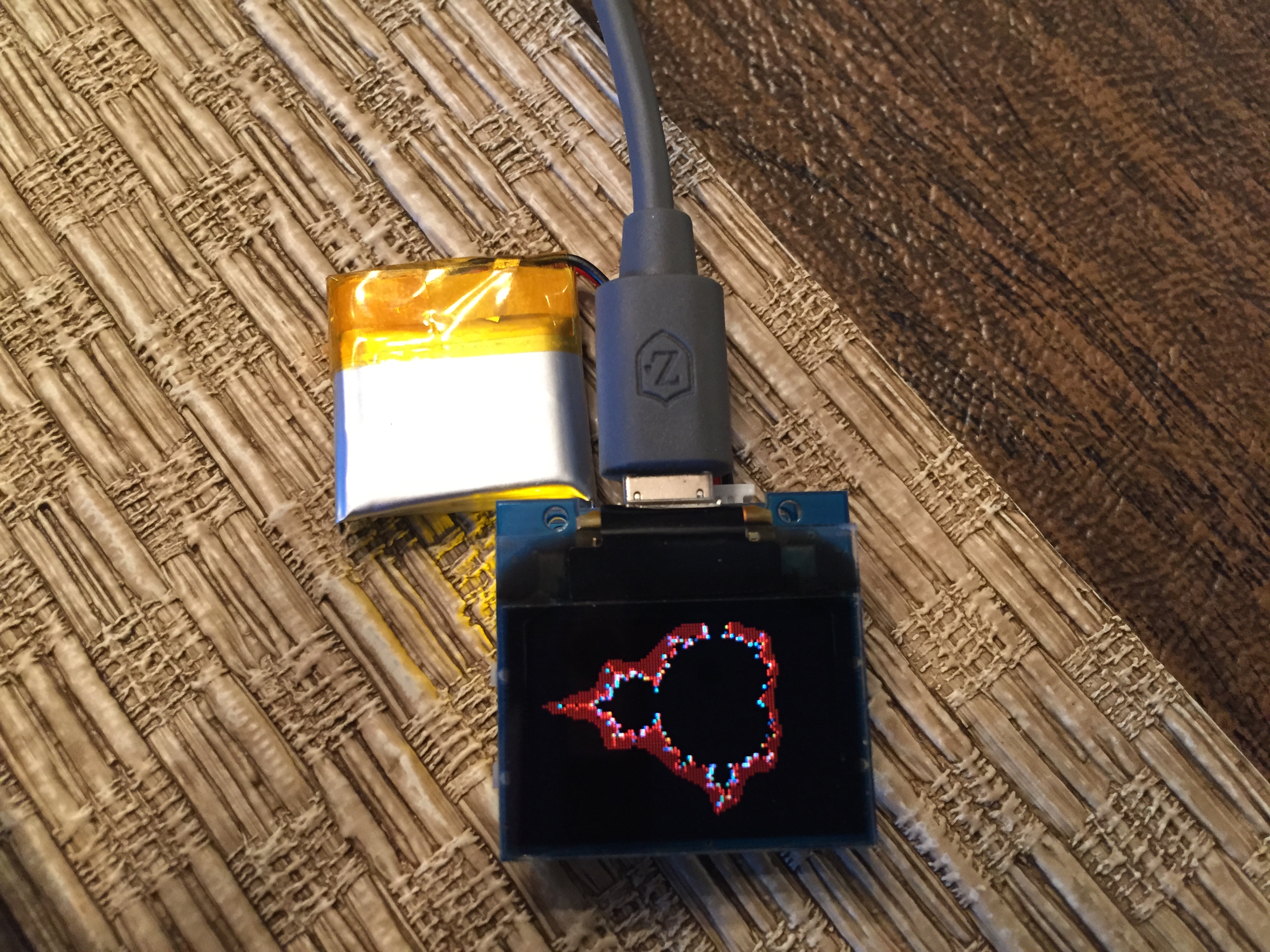
Another technique I like to use works well if the electronics have a USB micro B or USB C connector that can accept battery power. The Fibonacci 64 Nano board shown in the image above has a Seeeduino Xiao controller soldered to the back. The Xiao has a female USB C connector. In this wearable, I soldered the free ends of the battery holder wires to a male USB C connector breakout, and simply insert the connector into the microcontroller to power the board and LED. The connections between wires and USB connector are reinforced with hot glue and shrink tube for sturdiness, and wrapped with black tape for aesthetics. If you use this techinque, be very sure that you solder the wires from the battery holder to the male USB C connector with the correct polarity!
That’s it for this tutorial. I hope you find the technique useful, and enjoy creating functional wearables with it as much as I do!
One thought on “3D Printed Wearable Battery Holder”