Seven Segment Displays:
Seven segment displays have been around for more than a century (https://en.wikipedia.org/wiki/Seven-segment_display) and form the familiar shape of the numbers in digital watches, instrument panels and many other numerical displays. They’ve been replaced in many cases by screens, but from an efficiency standpoint it’s hard to argue with the brevity of encoding the state of a numerical display in only 7 bits of information (each segment on or off)
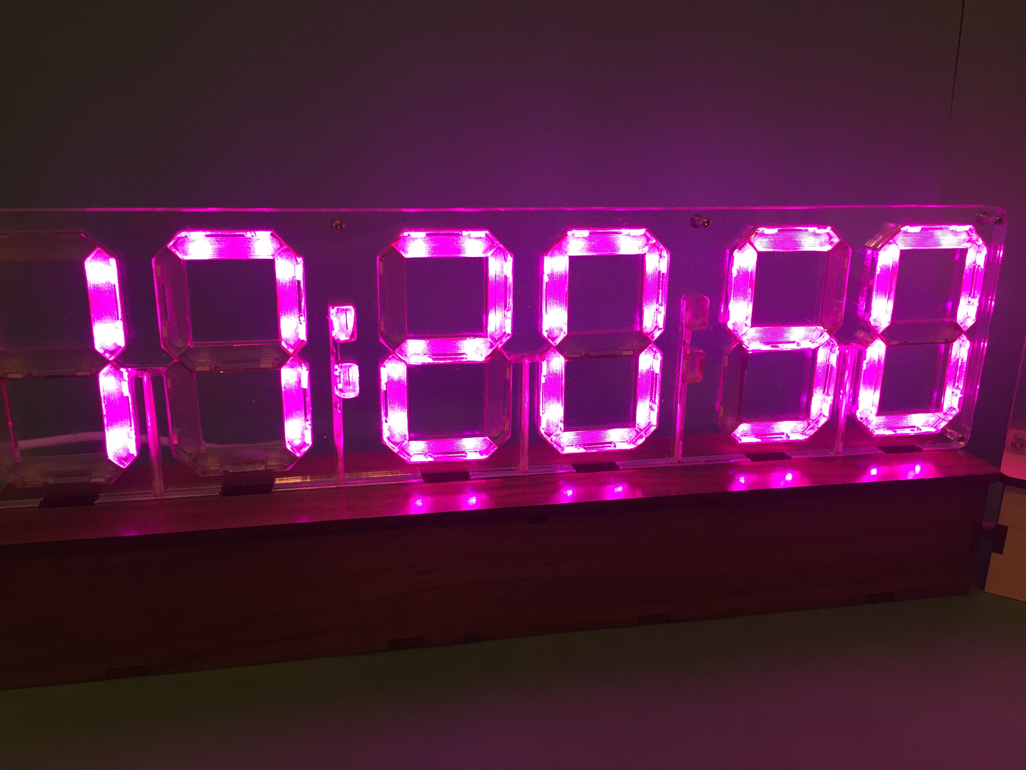
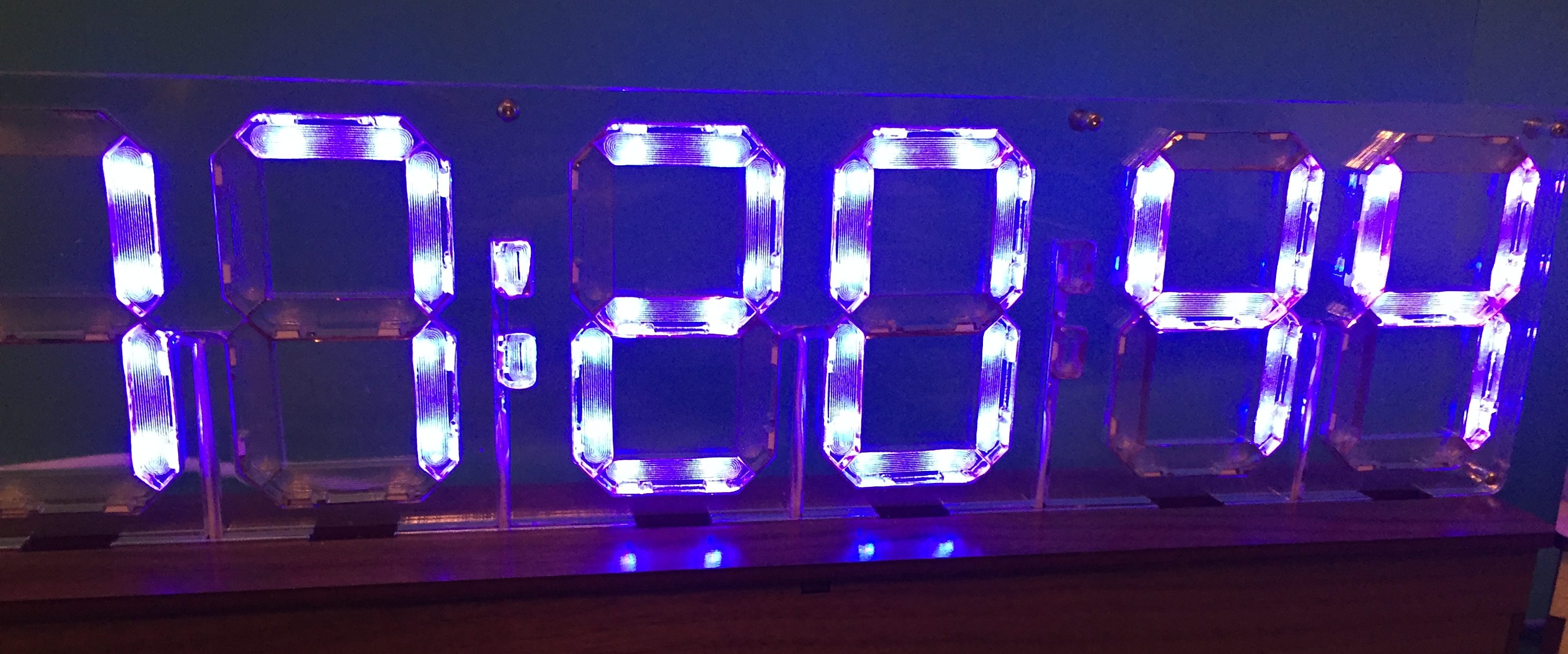
Most seven-segment displays are monochrome, so this edge-lit version adds visual interest by using the full color capabilities of cheap RGB LED strips to illuminate each digit and even each segment (or even half-segment) of the display in a different color. Embedding the clear acrylic segments in a larger acrylic frame allows you to see completely through the entire display, which another unique aspect of this project.
Disclaimer:
This build combines small dozens of small laser-cut acrylic pieces which fit together with very tight tolerances. It uses skinny (4mm wide) LED strips which must be soldered, bent, and then slotted in between those acrylic pieces. When assembling the parts you must be willing to force pieces into place, even though it feels like you are stressing the brittle acrylic. You must also be willing to remove and re-seat said pieces and LED strips when it turns out they *can’t* actually be forced into place. At some point during the assembly there is a strong likelihood that you will have to remove everything and re-solder your LED strip when you realize that forcing everything into place broke one of the wires away from your LED strip or created a short circuit.
With all of that said, this is a rewarding project if you are patient and willing to rework the alignment until everything slots into place.
This write up describes the build of the 6-digit display. It’s a bit easier to build the 4-digit display, and the steps are basically the same for both, so it’s probably best to start with the 4 segment display unless you feel very confident.
Components:
The quantities required depend on whether you’re building the 4-digit or 6-digit display.
- 1/8″ thick sheet wood for laser cutting
- 1/16″ clear acrylic for laser cutting
- 1/4″ clear acrylic for laser cutting
- Skinny (4mm wide) SK6812 3535 RGB LED strip with 60 LEDs/m (like this one)
- Adhesive vinyl foil ***THAT IS NOT CONDUCTIVE*** (I used this Cricut adhesive foil)
- 26 AWG solid hookup wire with white insulation
- 30 AWG stranded wire with white insulation
- A tiny amount of scotch tape
- 5 or 7 x 12mm M2 screws and M2 nuts
- MicroController capable of controlling the LED strip
- Power supply for MicroController and LED strip.
- Wood glue
- JB Weld (or similar) glue that can attach acrylic to wood
- 3-4 x M3 Screws and M3 nuts (optional but useful)
Tools:
- Soldering iron/solder
- Wire cutter/stripper
- Laser cutter (or an online service like Ponoko)
Design Files:
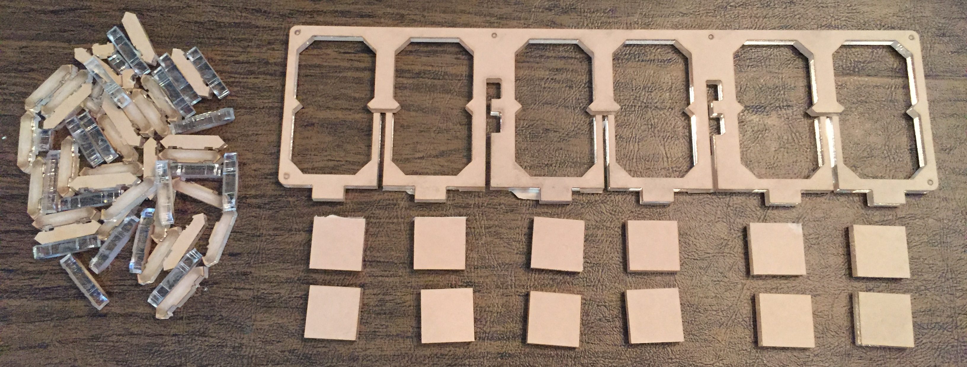
The zip file below contains six vector files for laser cutting, three apiece for the 4-digit or 6-digit build. The laser cut shapes are sized to exactly fit the LEDs and capacitors in a 60 LED/meter 3535 sized strip, so do not resize them before laser cutting them.
- Cut SevenSegmentBase4Digits.svg or SevenSegmentBase6Digits.svg from 1/8″ wood.
- Cut EdgeLitSevenSegment4Digits.svg or EdgeLitSevenSegments6Digits.svg from 1/4″ clear acrylic sheet.
- Cut EgeLitSevenSegmentCover4Digits.svg or EdgeLitSevenSegmentCover6Digits.svg from 1/16″ clear acrylic sheet.
Note:
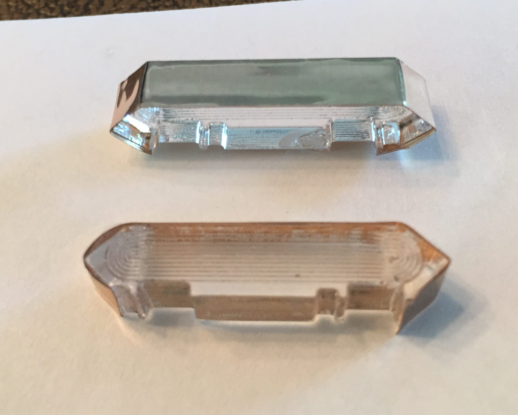
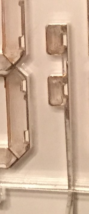
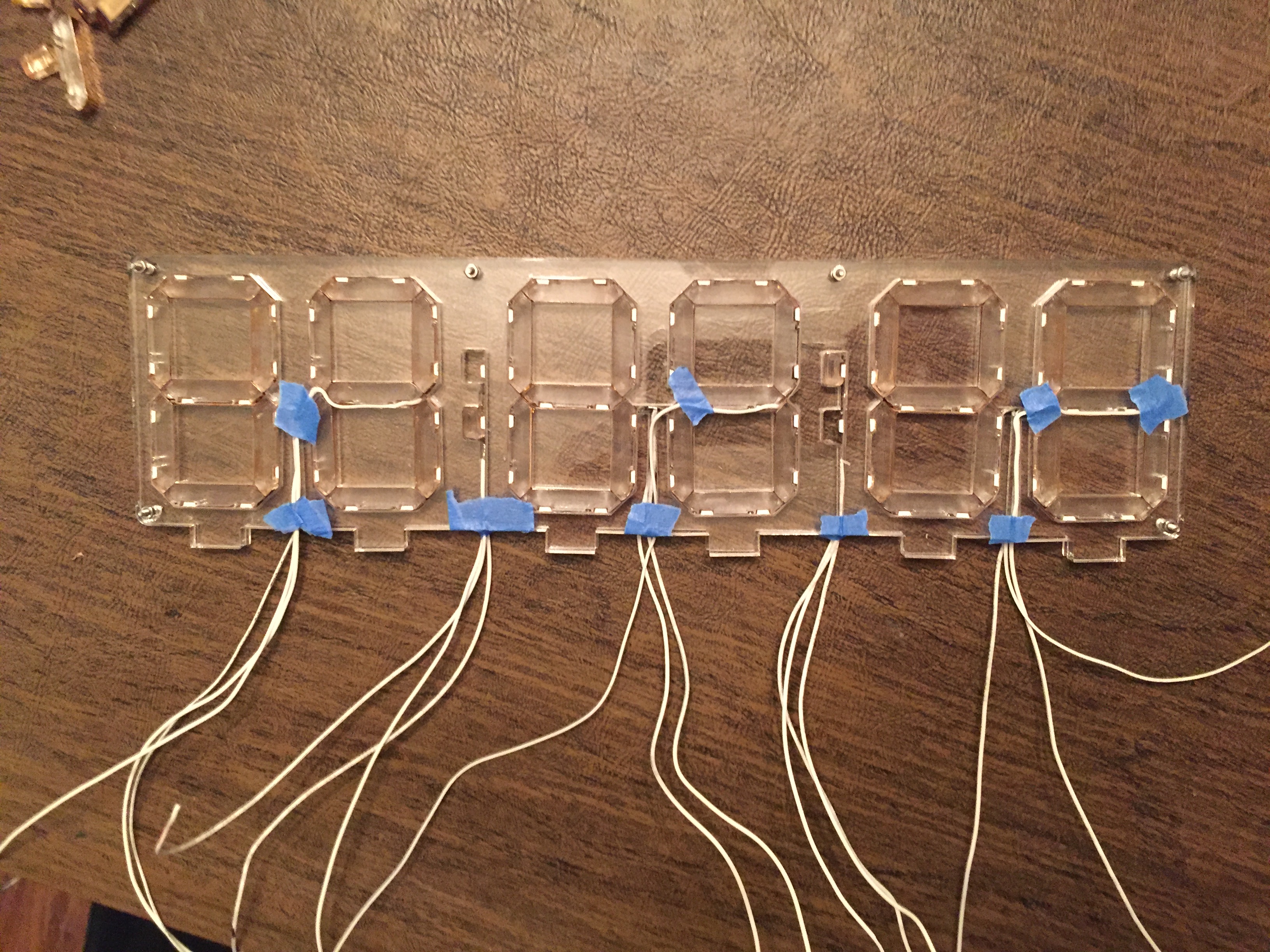
The tolerances for this project are very tight, and the segments have notches that are exactly spaced and *just* large enough to hold the LEDs and capacitors on the acrylic strip (see image below):
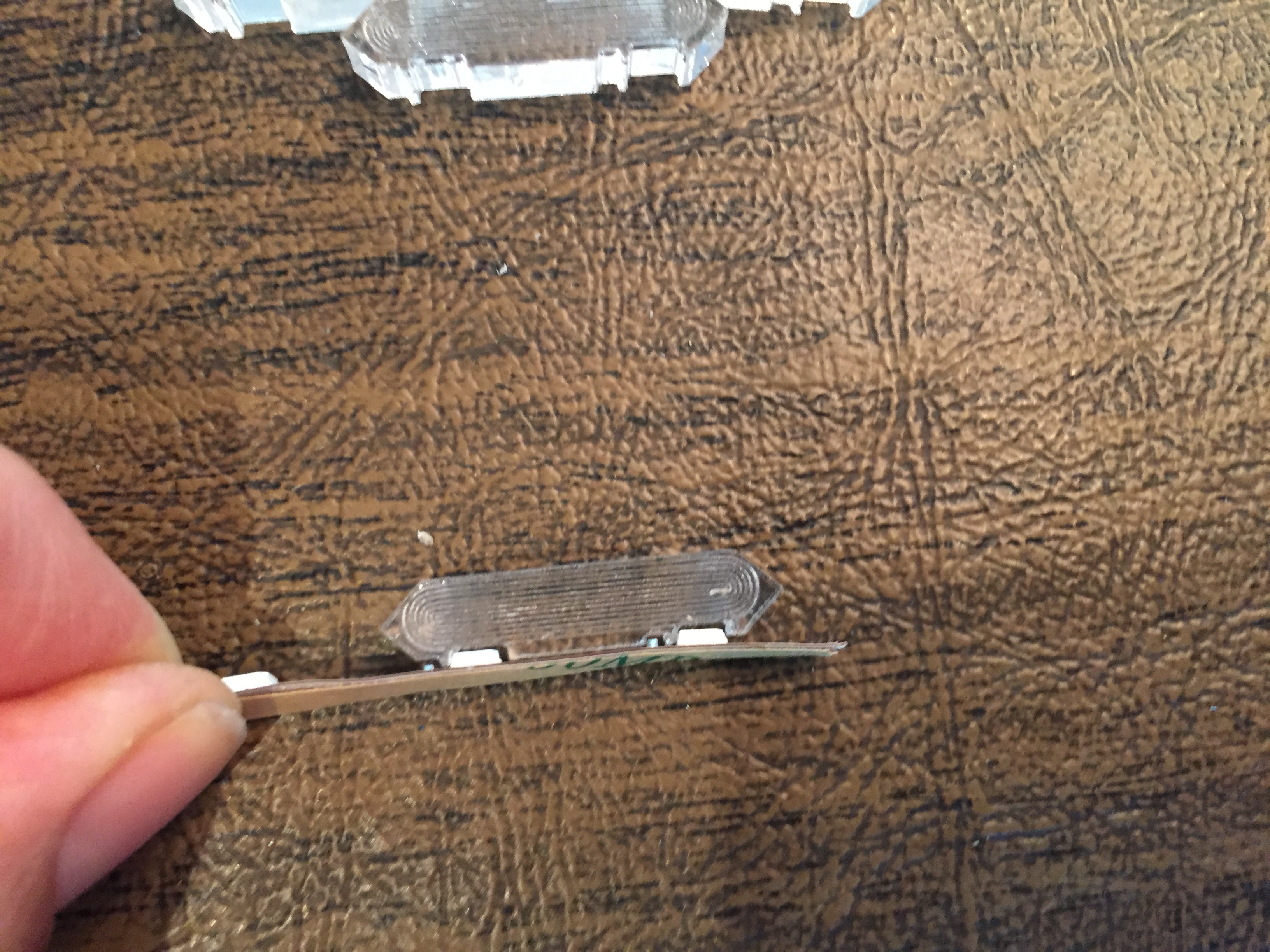
Because LED strips vary between manufacturers, you will want to check the spacing and size of the LEDs and capacitors on your LED strip to confirm that they align with the notches shown in the SVG file. You can test the design before doing the laser cutting by printing out a scale image of the segments and seeing if the notches align with your LED strip. If yours do not fit exactly, the build will not work. If you are good with CAD, you should be able to modify the spacing of the notches in the SVG file to match your strip, however.
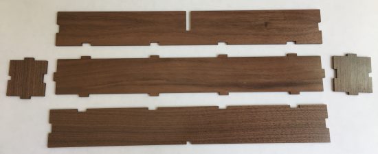
Step 1: Cut and Build the Enclosure
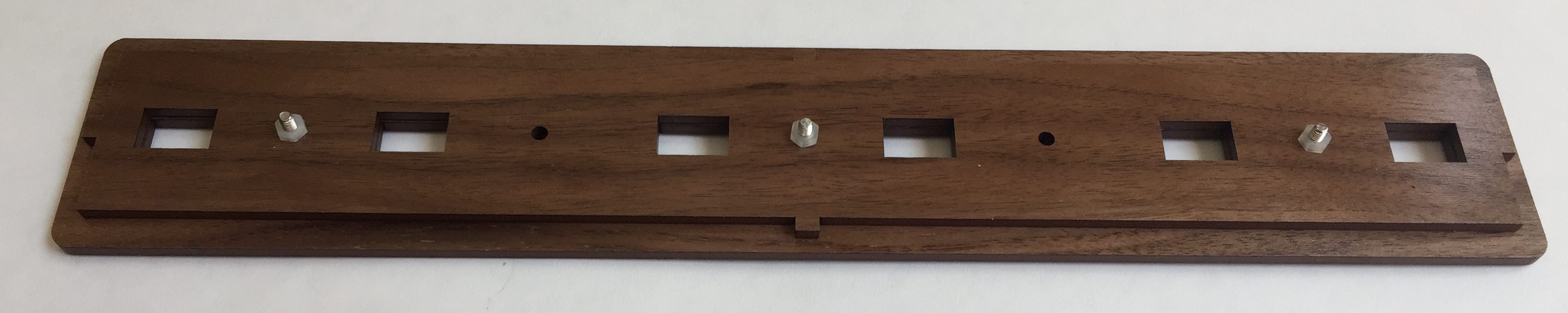
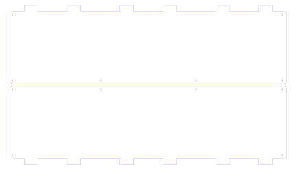
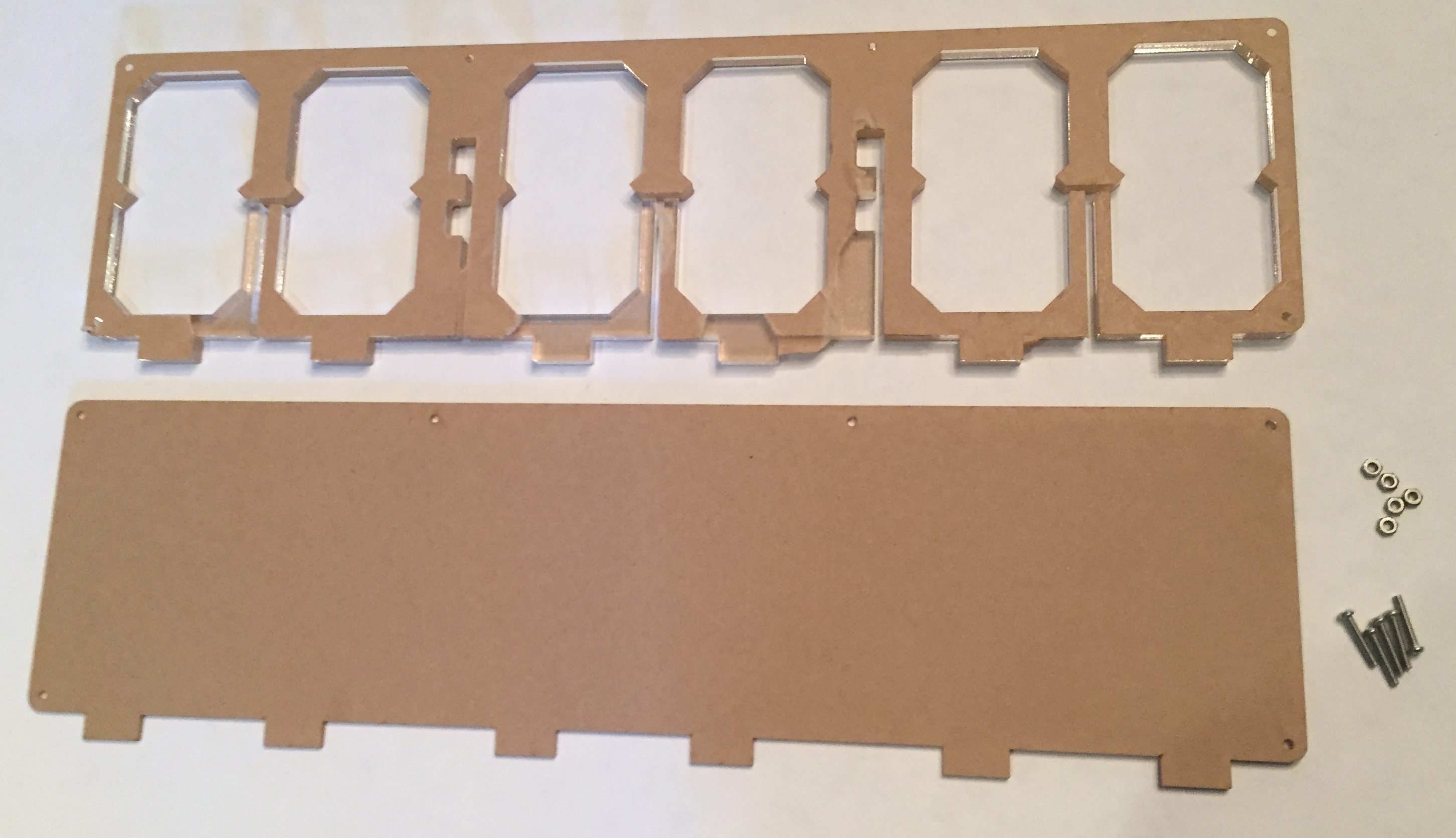
Cut the enclosure pieces from 1/8″ wood of your choice. I forgot to photograph this step, but first take the outer and inner lid pieces (outlines shown below), and bond them together with wood glue so that the holes all line up with each other. The larger piece is the outer part of the lid and the smaller piece will sit inside the enclosure.

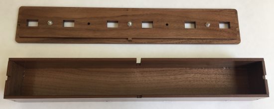
Note that the placement of the holes is not totally symmetric and so the orientation of the lid pieces matters. Make sure *ALL* the holes line up when you align the pieces. Clamp the pieces together or use M3 screws and nuts through the holes to fasten them together while they dry.
Assemble the body of the enclosure by laying out the pieces as shown below, applying glue to the edges, and sliding the matching slots and tabs together. Clamp or tape the pieces together while the wood glue dries.
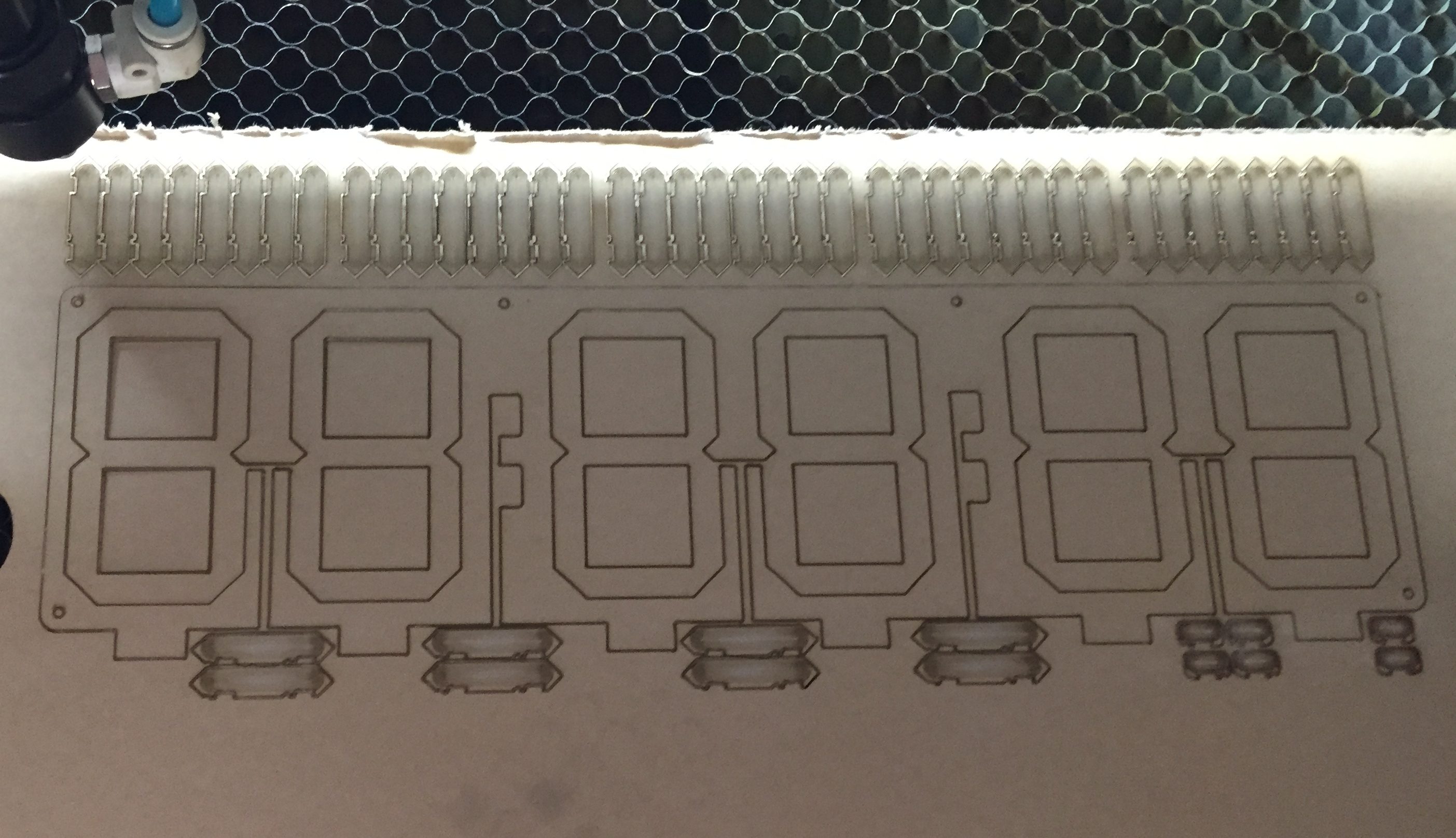
Step 2: Laser Cut the Acrylic
Cut the cover pieces from 1/16″ clear acrylic sheet:
Cut the main clock body and segments from 1/4″ clear acrylic sheet. The pieces contain very small details, so make sure that the cut is clean enough that the small bumps don’t break off when you separate the pieces.
Go ahead and peel any protective paper off of *all* the acrylic pieces. It will take you a while, and hopefully you will still have some fingernails left when you are done.
Step3: Cover the Edges of All Small Acrylic Segments
The acrylic segments and dots are very small and will allow a lot of light to bleed out if we don’t mask off the edges. We will use the *NON CONDUCTIVE* adhesive foil for this.
I used a vinyl cutter to cut the foil into long 1/4″ strips. If you don’t have a vinyl cutter you can use an exacto knife or scissors to cut 1/4″ inch strips
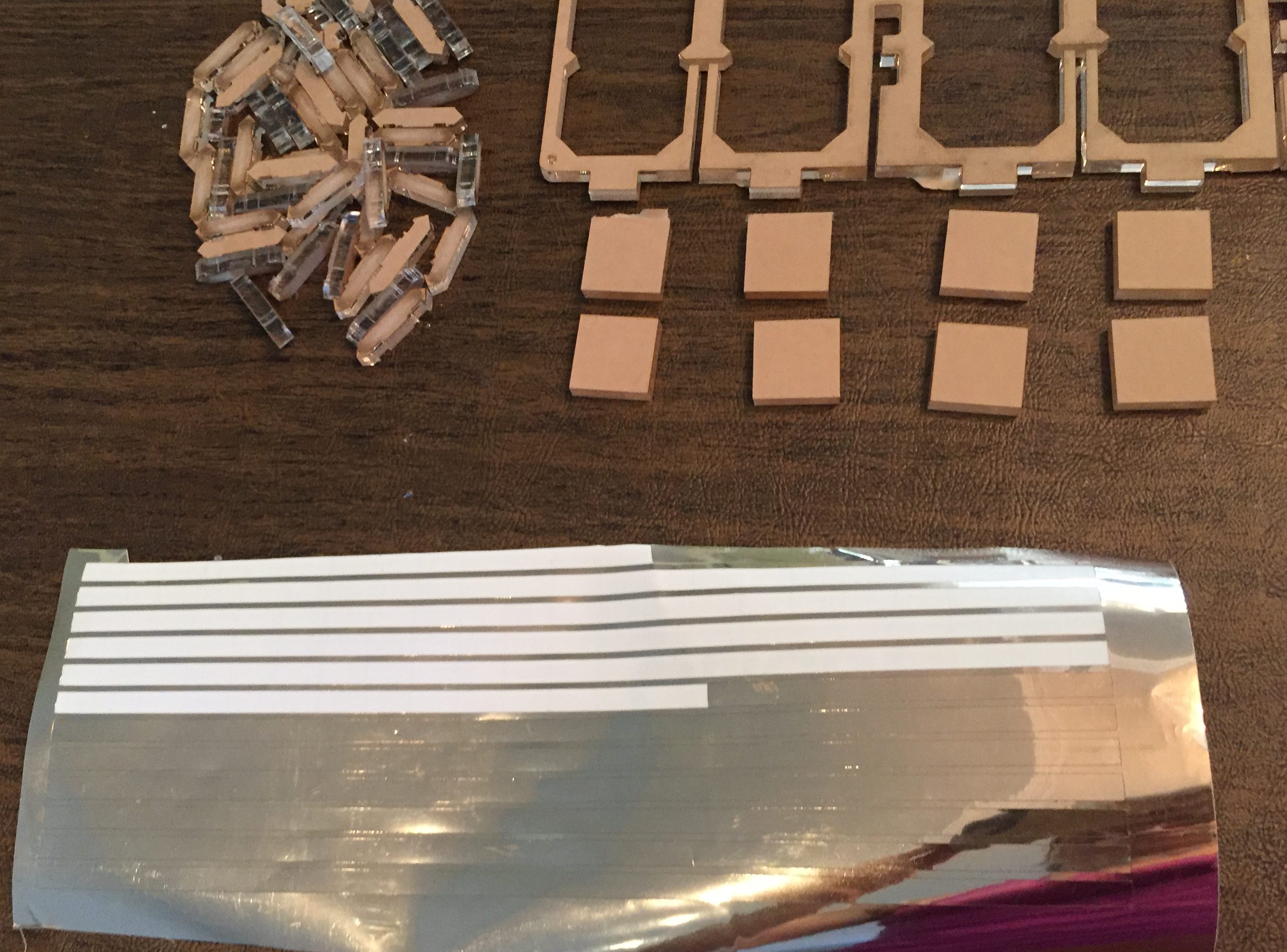
Use the foil strips to cover every edge *except the one with the notches* of the small segments and dots. Its easiest to cover the edges of the acrylic with a long piece of the vinyl foil, and smooth it out with firm pressure before cutting off the excess.
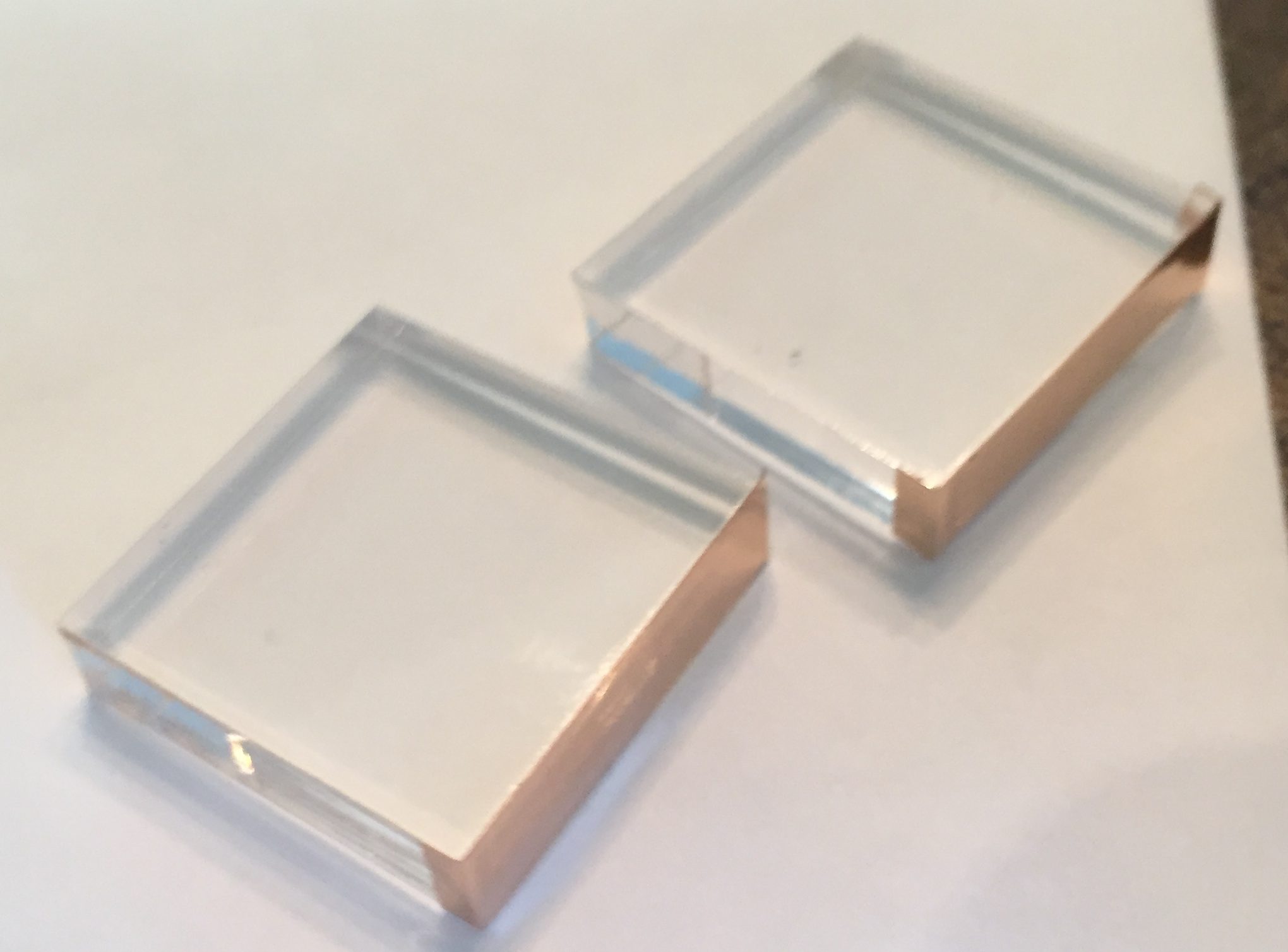
Additionally, take 4 or 6 of the acrylic squares (depending on whether you have a 4 or 6 digit display) and cover *one* edge of each square with a vinyl foil strip:
Step 4: Attach the Cover and Main Acrylic Frame
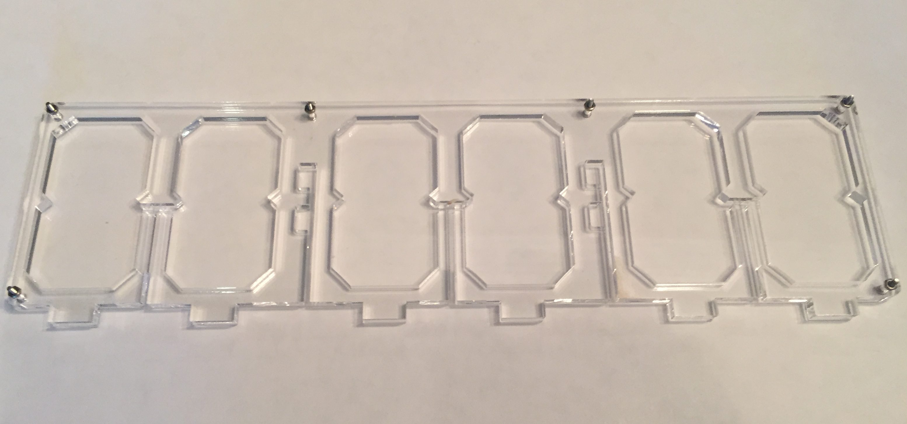
Take one of the 1/16″ acrylic cover pieces and the large 1/4″ piece and line them up so the small holes are on top of each other. Insert an M2 screw in each hole so that the screw enters through the cover piece and exits the 1/4″ acrylic frame. Screw the two acrylic pieces together as shown below. Note the orientation of the two dots relative to the slot below them. Be sure to orient the frame on top of the cover so that the two dots are to the left of the slot. We are looking down at the back side of the display.
Step 5: Solder the LED Strips
From the LED strip cut two or three smaller strips (for the 4 or 6 digit displays respectively) of 28 pixels each to illuminate the digits, and one or two segments of 2 pixels each to illuminate the dots. Be sure to keep the solder pads on the data input side of the strip. Trim the output end of the strip fairly close to the final capacitor – no need to keep the pads there – because there is *just* enough space for the strip to fit. Try to avoid including any joins (which usually occur every 30 pixels) within the strip as exact spacing of the LEDs is important.
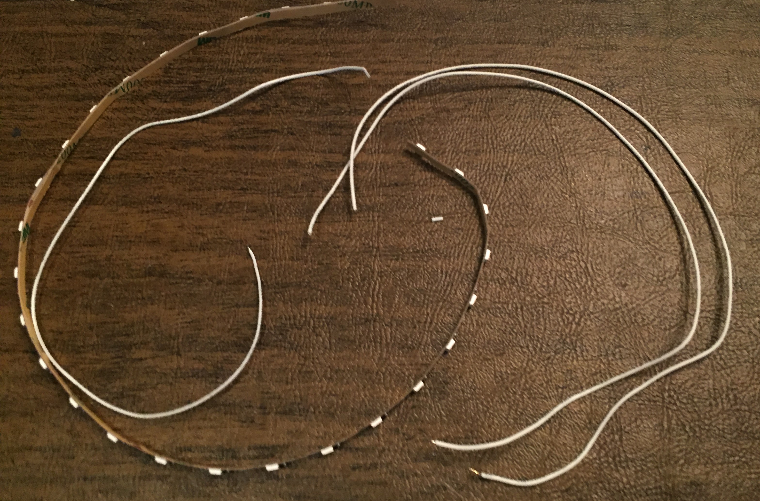
For each 28 pixel strip, cut two lengths of 26 AWG solid hookup wire and one length of 30 AWG stranded wire, all with white insulation. Use lengths of about 8 inches. We’ll use the stranded wire for signal, and the hookup wire to provide power.
On the input side of the strip, apply solder to the signal pad ONLY, then strip and tin the tip of the 30 AWG stranded wire, and solder it to the pad, taking care that there are no stray strands shorting out to the 5V or GND lines.
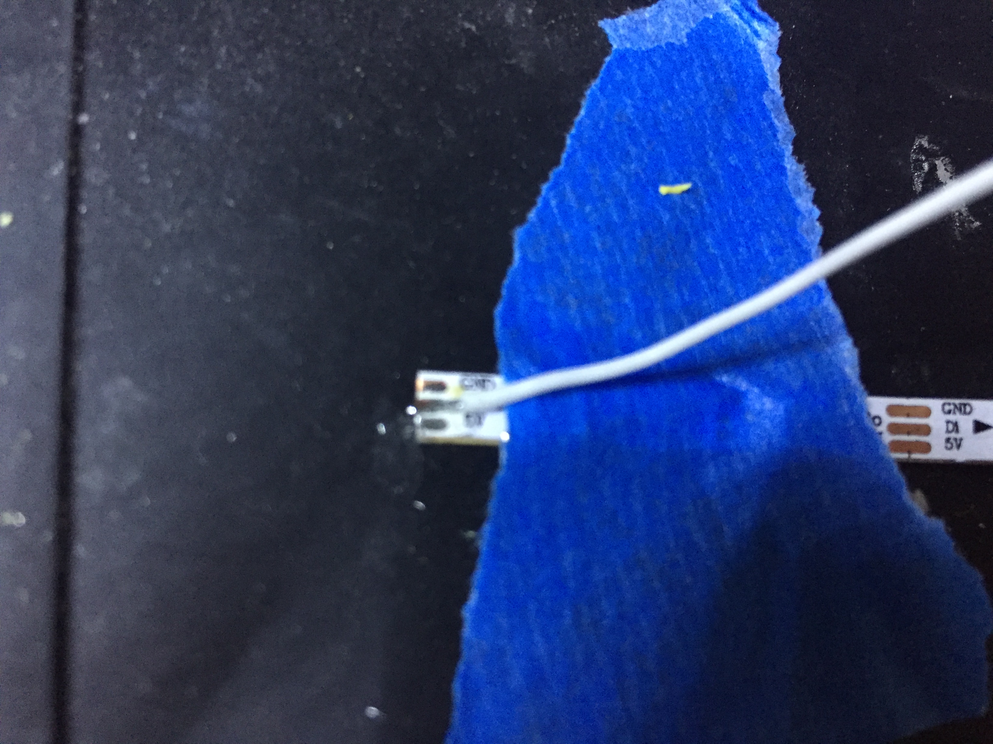
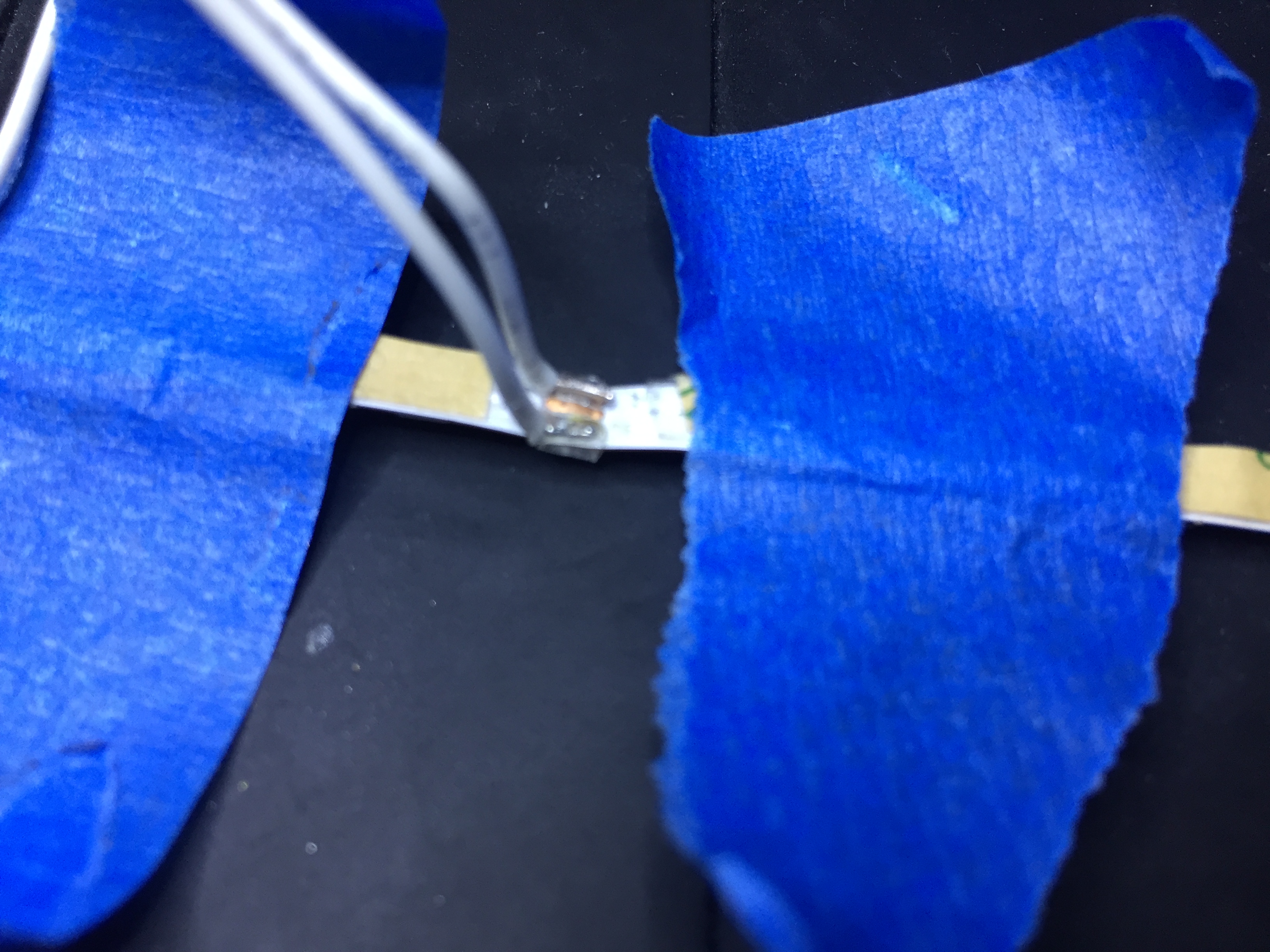
We will solder the 26 AWG hookup wire to the *BACK* side of the strip. Start by turning the pad over, and cutting away the paper that covers the set of three pads in the exact middle of the strip. There should be 14 LEDs on either side of this set. Then use an exacto knife or something similar to carefully scrape away the 3M adhesive which will be covering the pads. You may be able to just pull up the adhesive and cut it with a small scissors, but be sure it is completely removed from the pads.
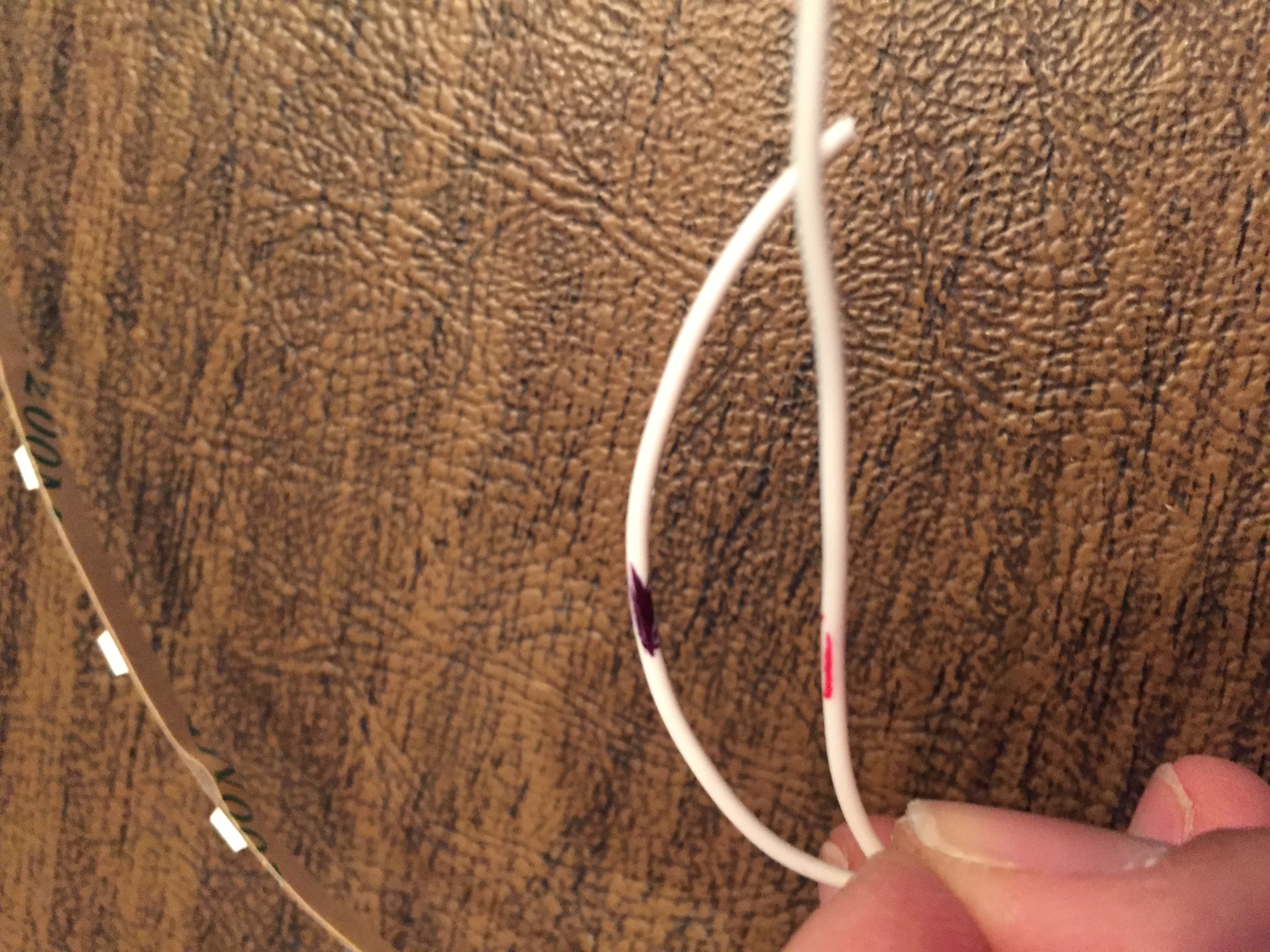
Now apply solder to the 5V and GND pads you just cleared on the *BACK* side of the LED strip, strip and tin the tips of the 26 AWG wires, then solder them to the power pads. Carefully bend the wires upwards to a 90 degree angle just past the solder join.
Since both power wires are white, mark the ends with a sharpie so that you will be able to tell them apart later.
It’s a good idea to test the connections now before placing the wire inside the display frame. Make sure all the LEDs light up and there are no shorts. The next step is to assemble the acrylic pieces and LED strips for the digits in the display. We’ll repeat the same process for each pair of digits.
Step 6: Embed the LED Strip and Segments for the Digits in the Acrylic Frame
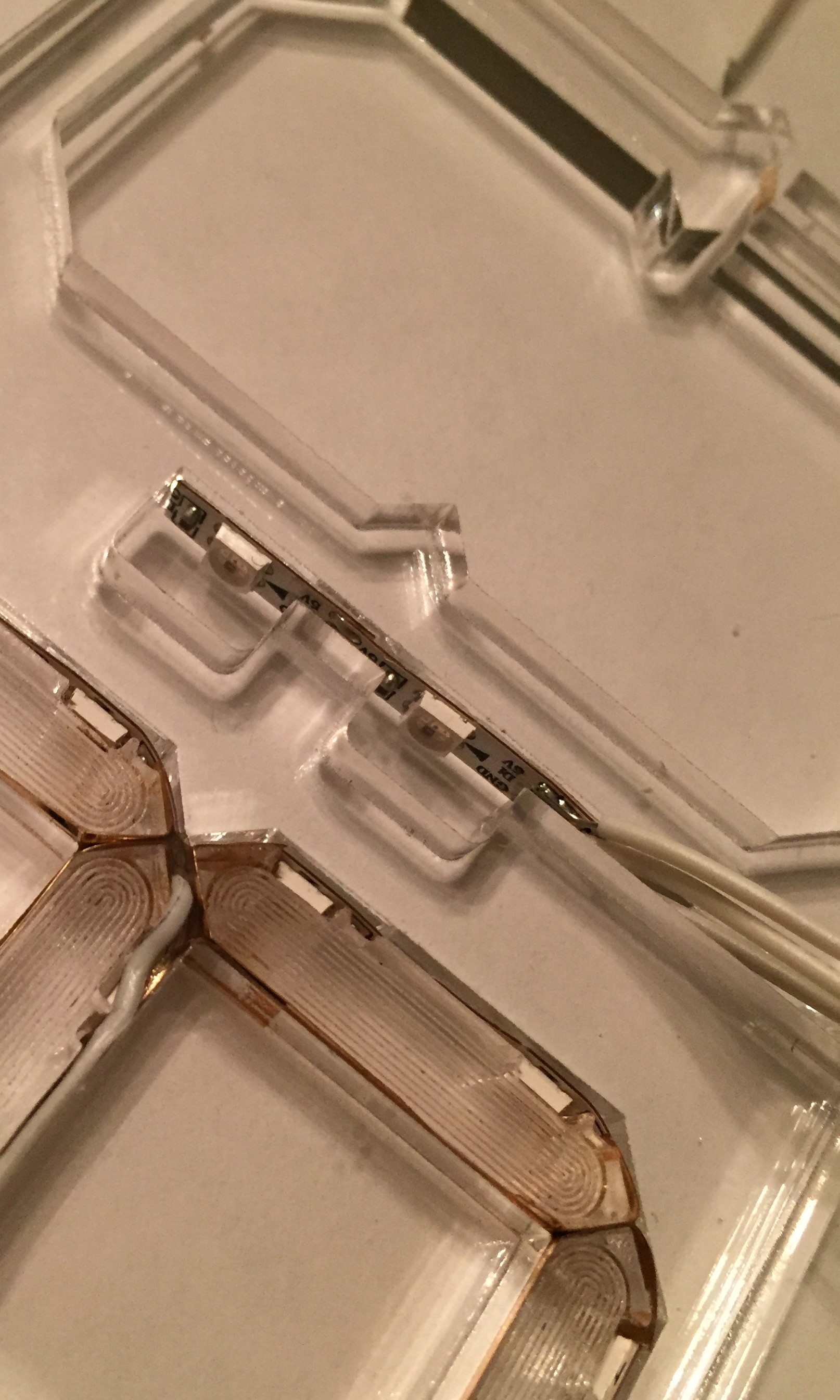
Now we’ll start adding the LED strip and acrylic segment pieces into the frame. We’ll start from the middle of the strip and work outwards with each half of the strip following the path shown below:
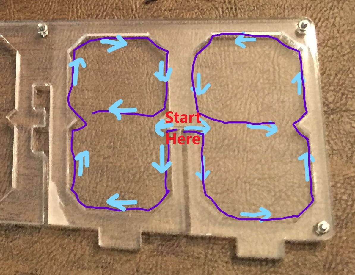
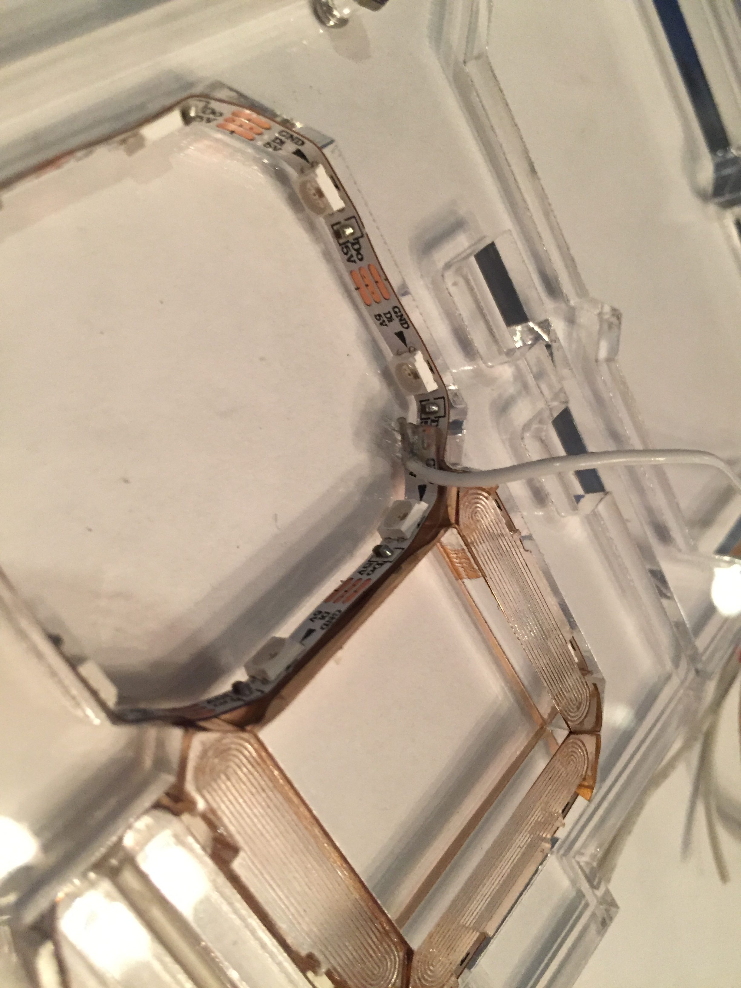
Take the 28 pixel LED strp and slot it into the frame as shown so that the power wires fit into the slot hanging down between the digits, and there are 14 LEDs available for each digit. The input end of the LED strip, which contains the signal wire, should go inside the rightmost (from our current view) of the two digits. We will attach this LED strip around the perimeter of each seven segment display. Peel the paper away from the middle of the strip as you go, but only stick a small portion of the strip at a time, because you will probably have to remove and re-seat portions of it periodically to make sure the segment pieces fit properly.
Assemble one digit at a time, starting with the rightmost of the two digits (the one containing the signal input wire). Each of the seven small segments in the digit corresponds to two LEDs on the strip. Alternate sticking down two pixels of the LED strip, then adding one segment. Place all of the small segments with the etched side facing upwards. Edge lighting effects look much better if any etching is on the back side of the illuminated acrylic. If you’re not sure which side is etched, scratch both sides with a fingernail, and you should be able to feel the grooves on the etched side.
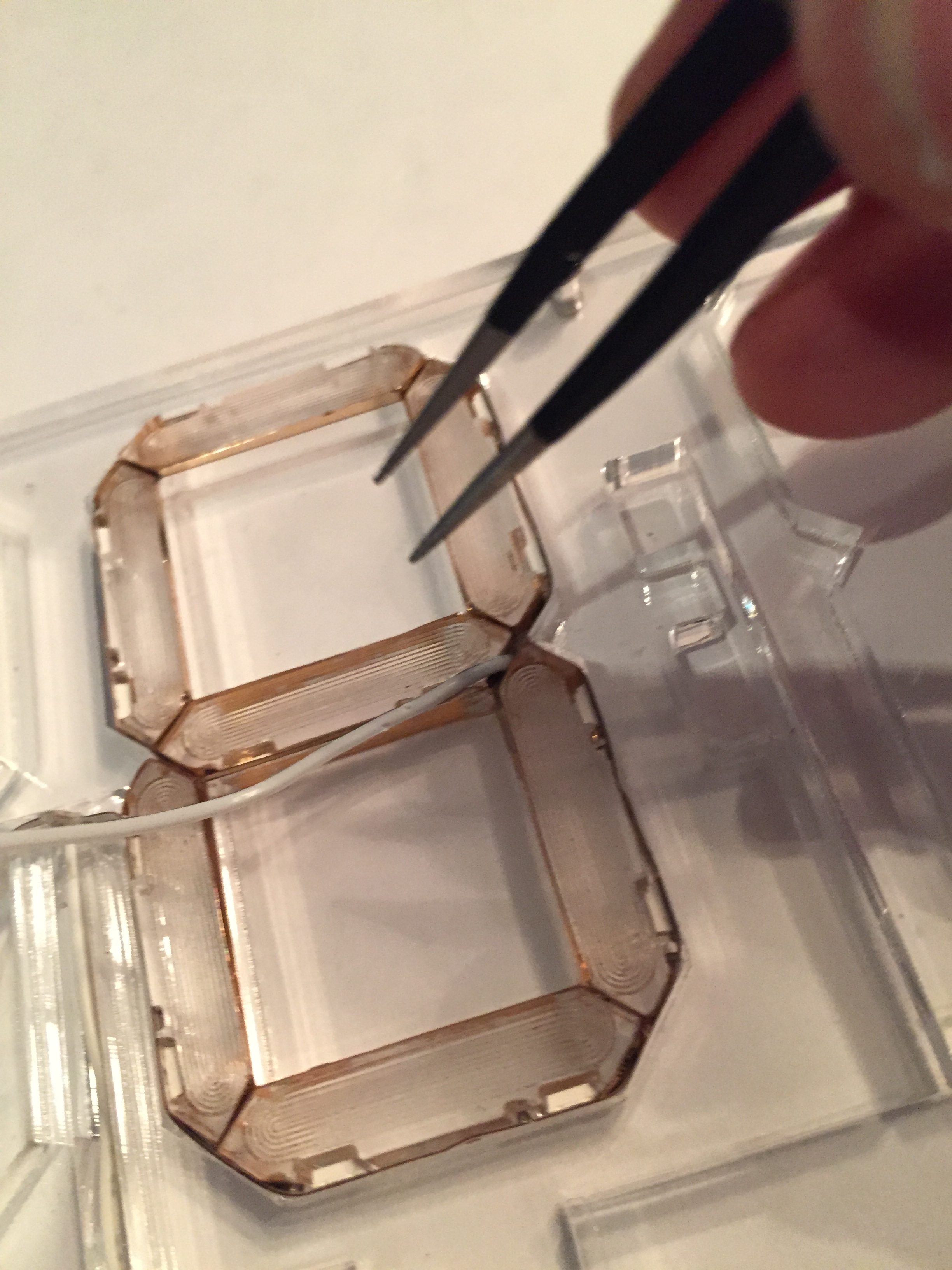
Place the segments into the frame as you go. It is important that everything fits snugly, so each time you stick down part of the acrylic strip, press the segment into place on top of the strip, and make sure the segments fit well into the perimeter of the digit. A small tweezers is helpful if you need to lift off and re-seat the LED strip.
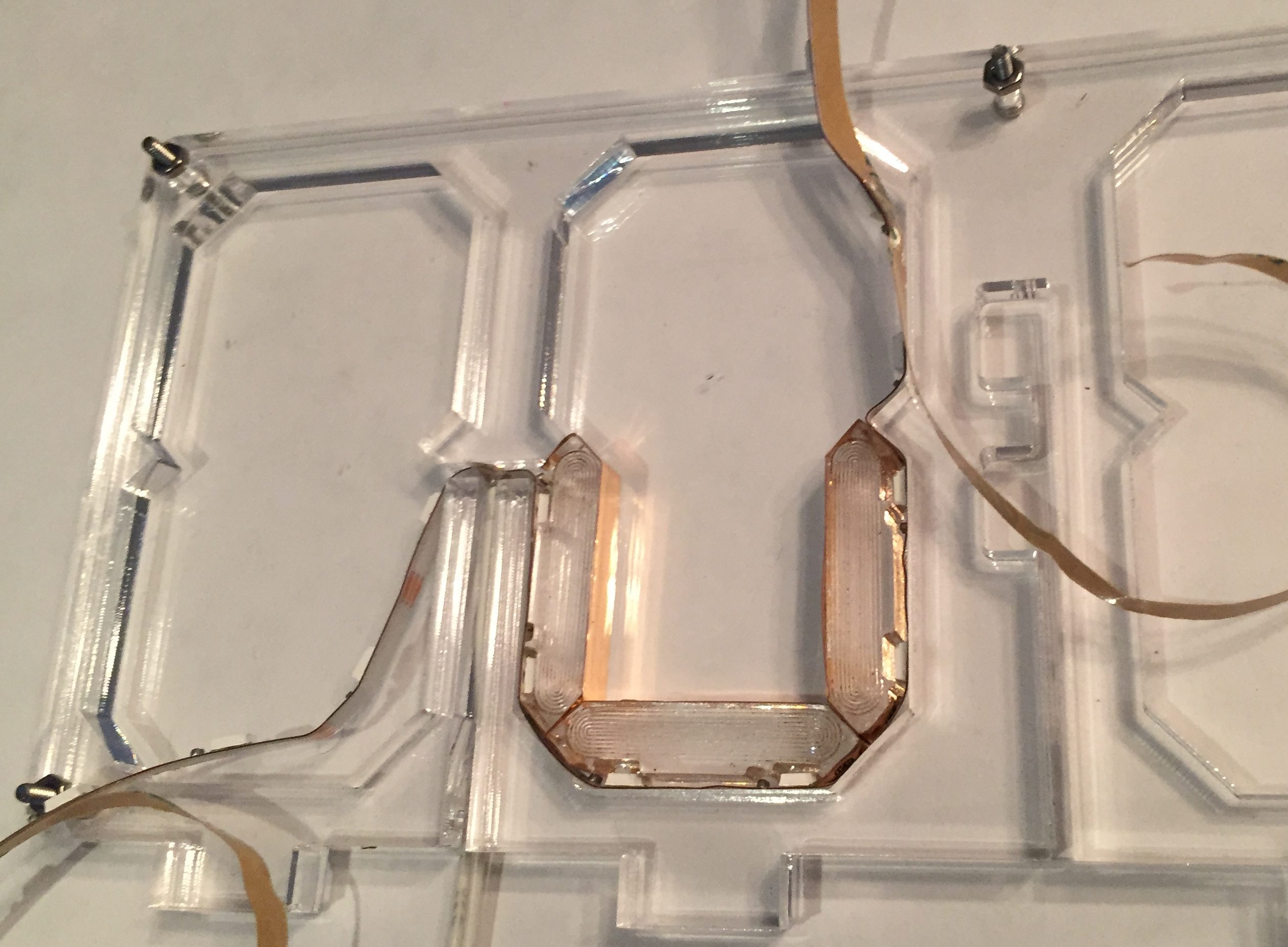
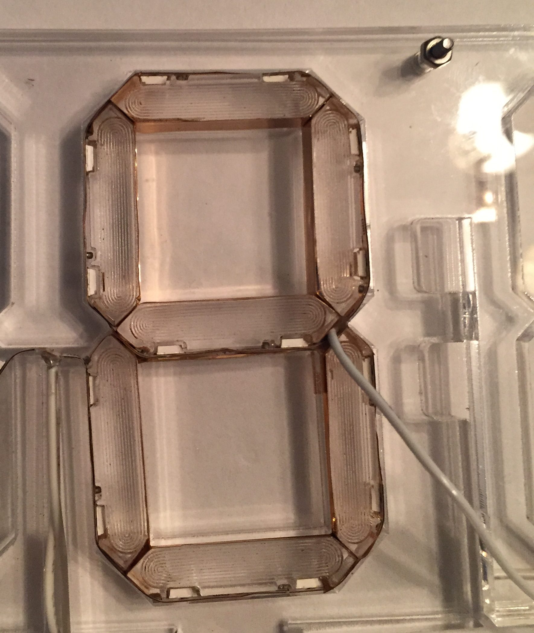
After the first three segments are in place, place an acrylic square in the middle of the bottom “loop” of the digit. Use the acrylic square that has vinyl foil covering one edge. The foil should be on the edge of the square closest to the middle of the digit. Its easiest to place the square by placing it into the upper “loop” and sliding it downwards until it rests between the segments.
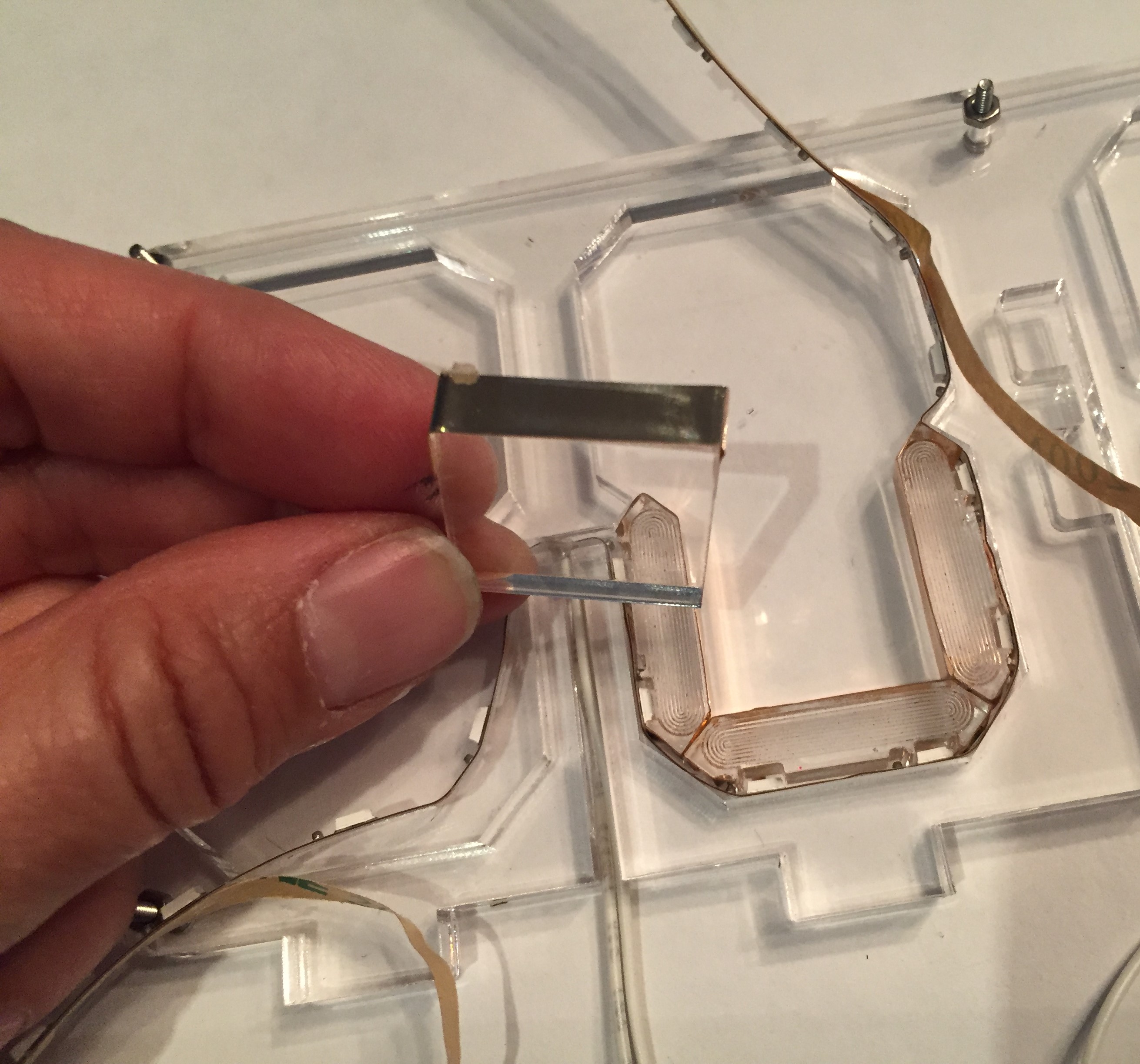
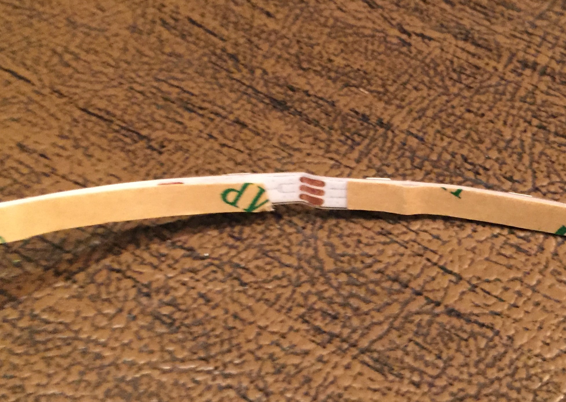
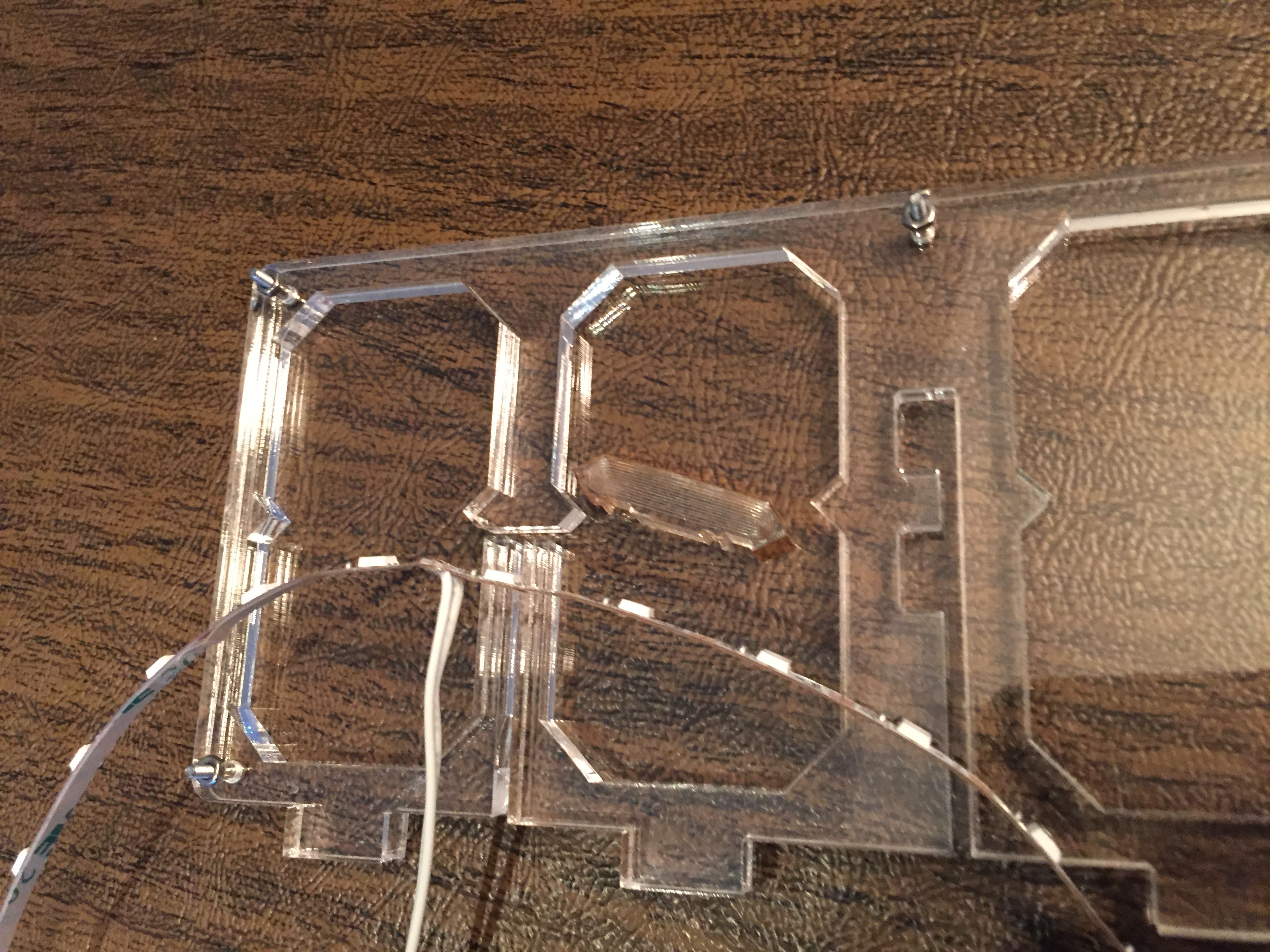
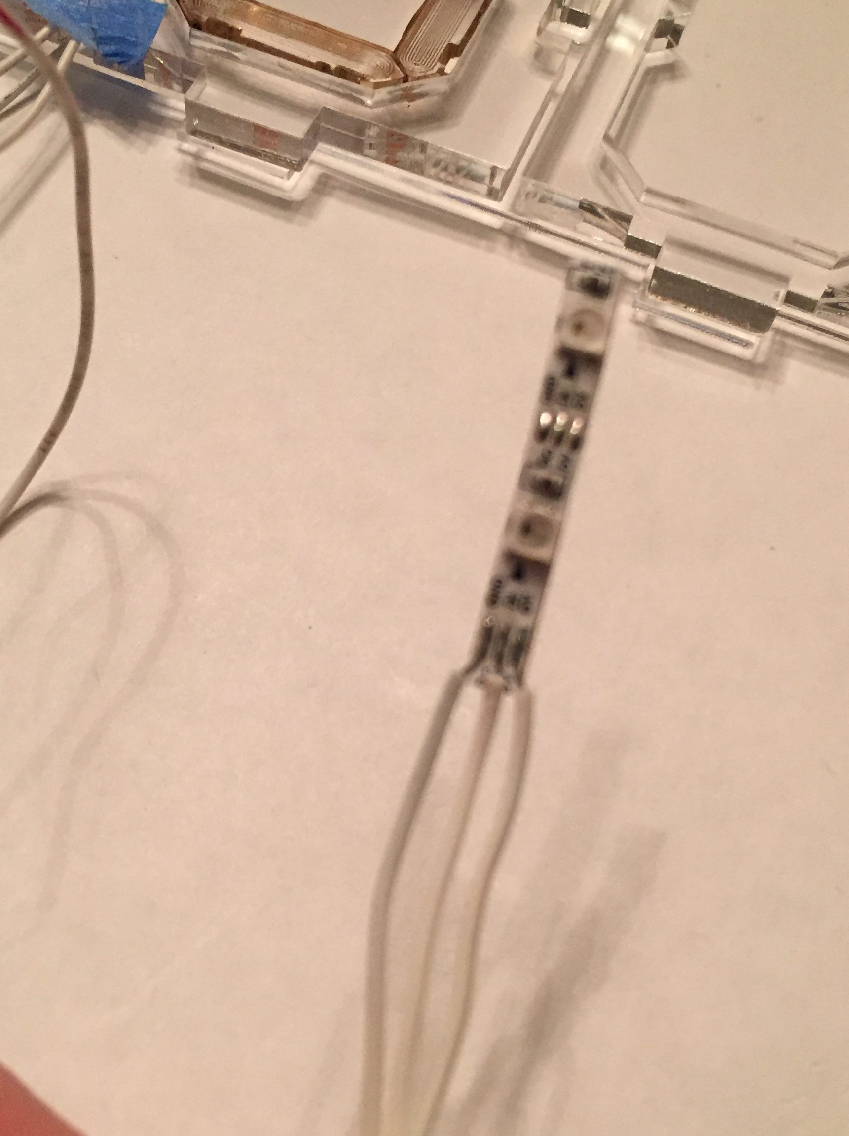
Continue attaching the rest of the LED strip around the perimeter of the digit as shown, but wait to insert the acrylic segment pieces. When you get to the very end, stick the last two pixels of the LED strip over the vinyl foil covering the top edge of the square. The very last set of solder pads on this portion of the strip will overlap the solder pads on a previous part of a the strip (see image below). Before sticking it down, it is important to place a *very thin* piece of insulation between the two parts of the strip. I cut a tiny piece of scotch tape and stuck it to the underside of the pads at the end of the strip.
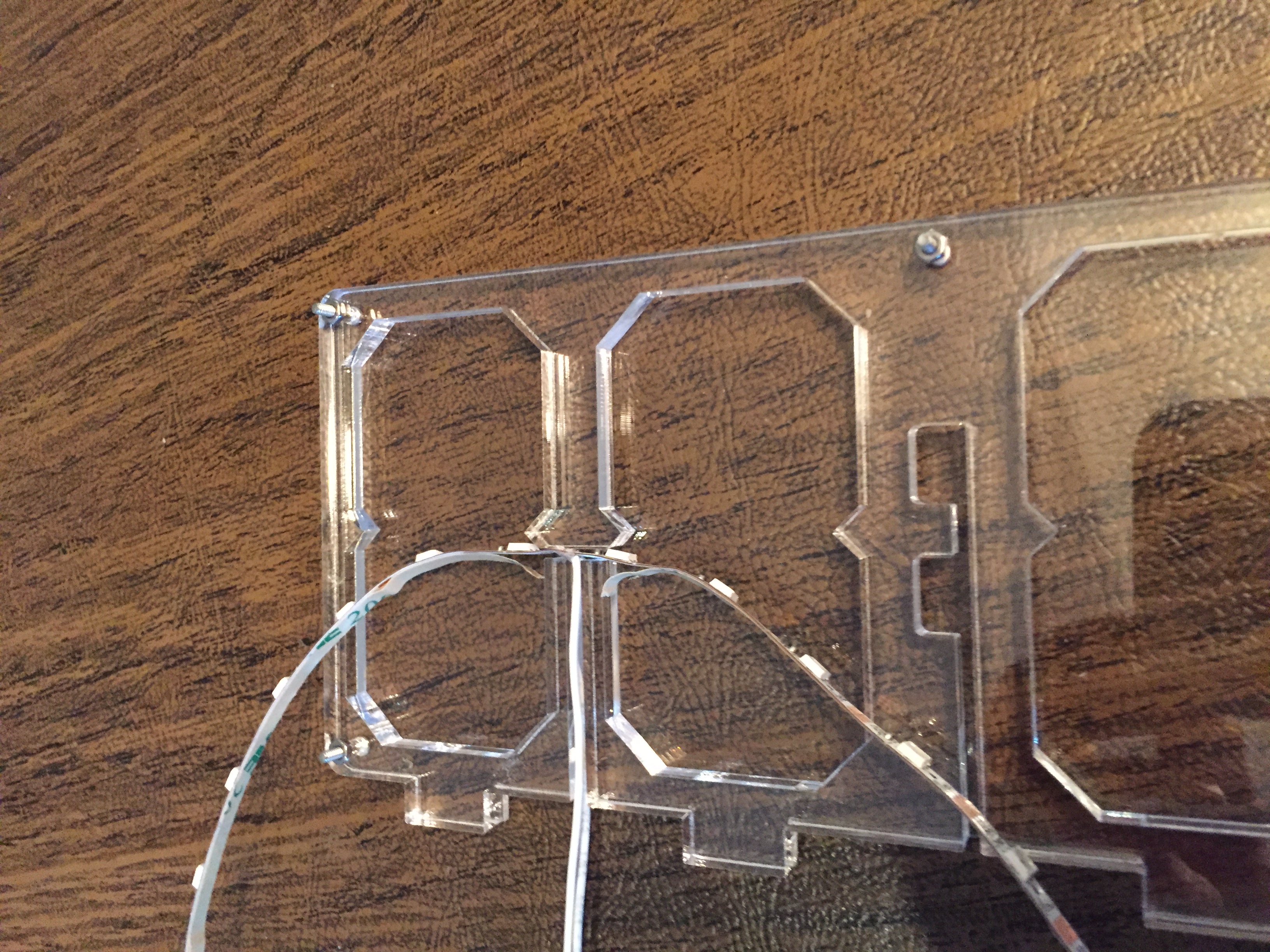
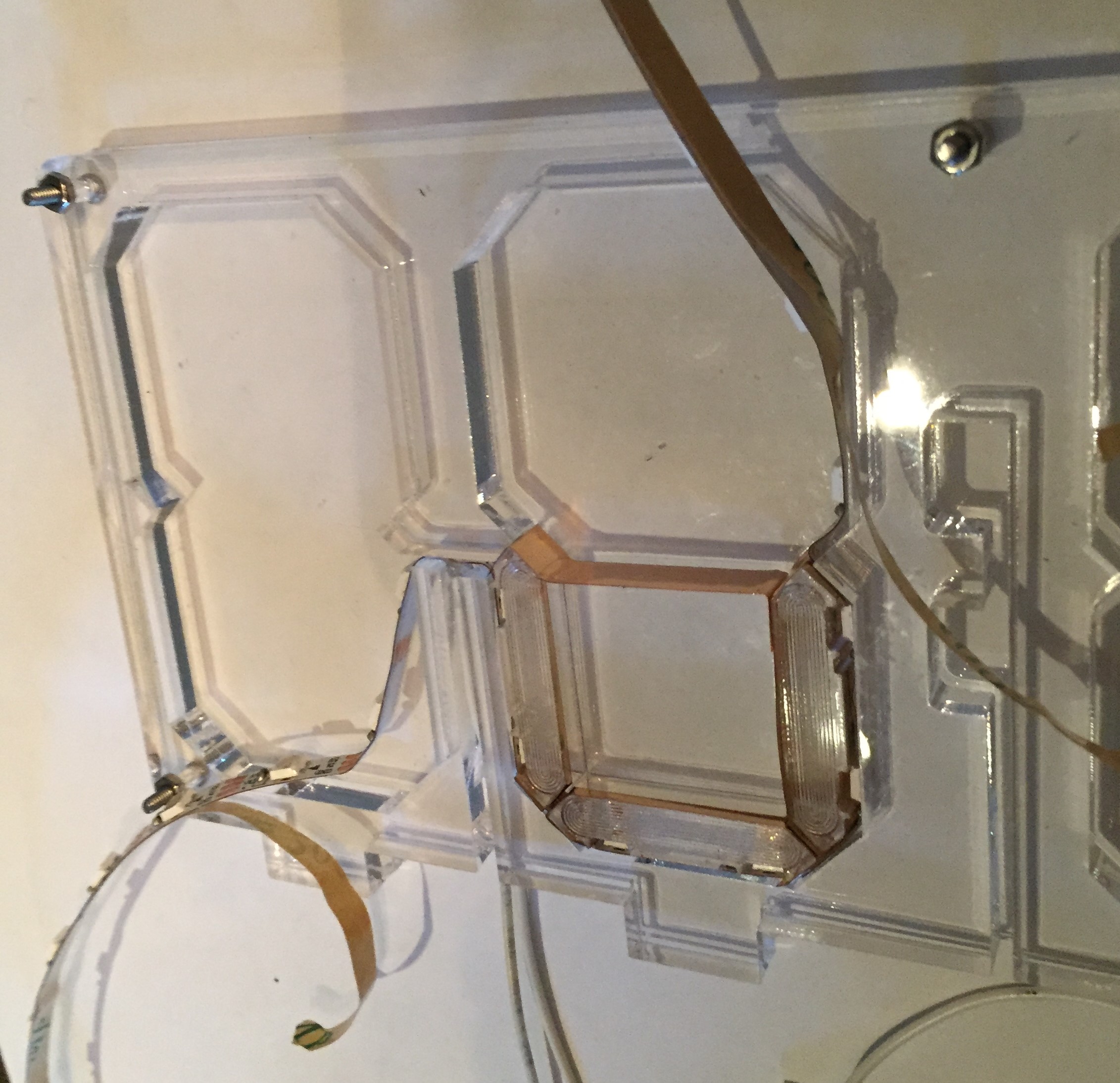
Add the last acrylic segment pieces. When you get to the end of the strip, be very careful when you place them so that you don’t dislodge the signal wire attached to the end of the strip. (I did this, and had to remove all the pieces and LED strip and start over. It’s not the end of the world, but it is a pain) Make sure the signal wire extends out of the digit, as shown below.
Slide the last square into place in the upper portion of the digit. This square does not have any vinyl foil on it. The fit will be quite snug. The easiest way to place the square is to push the bottom portion of the square in place first and apply light to moderate pressure (you shouldn’t have to break a sweat) downwards while slotting in the top of the square. The vertical channels between the digits for the wires make the lower portion of the digit a little more flexible than the top. You’ll have to use your judgment about how hard you can push the piece into place if it doesn’t go in easily.
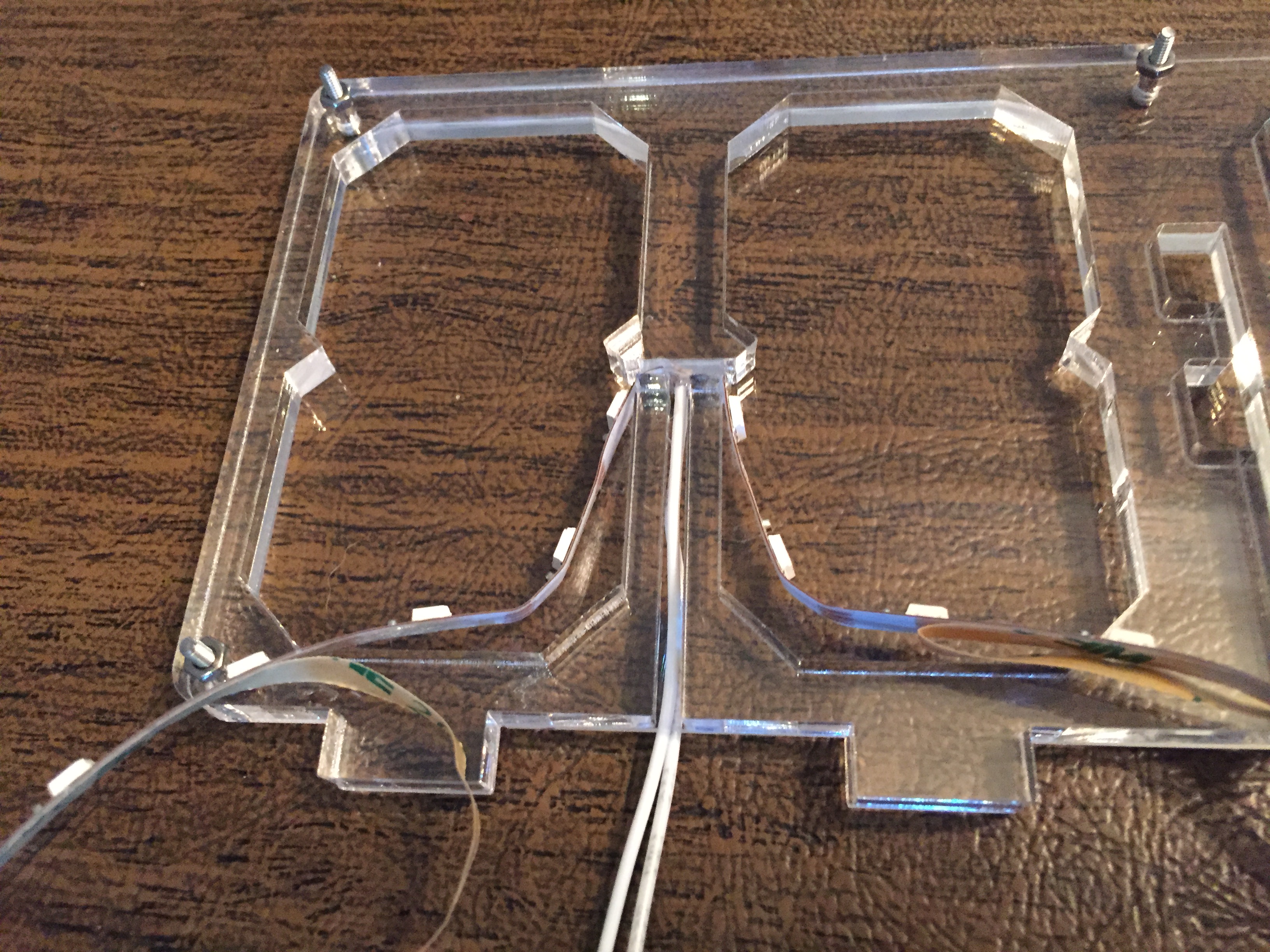
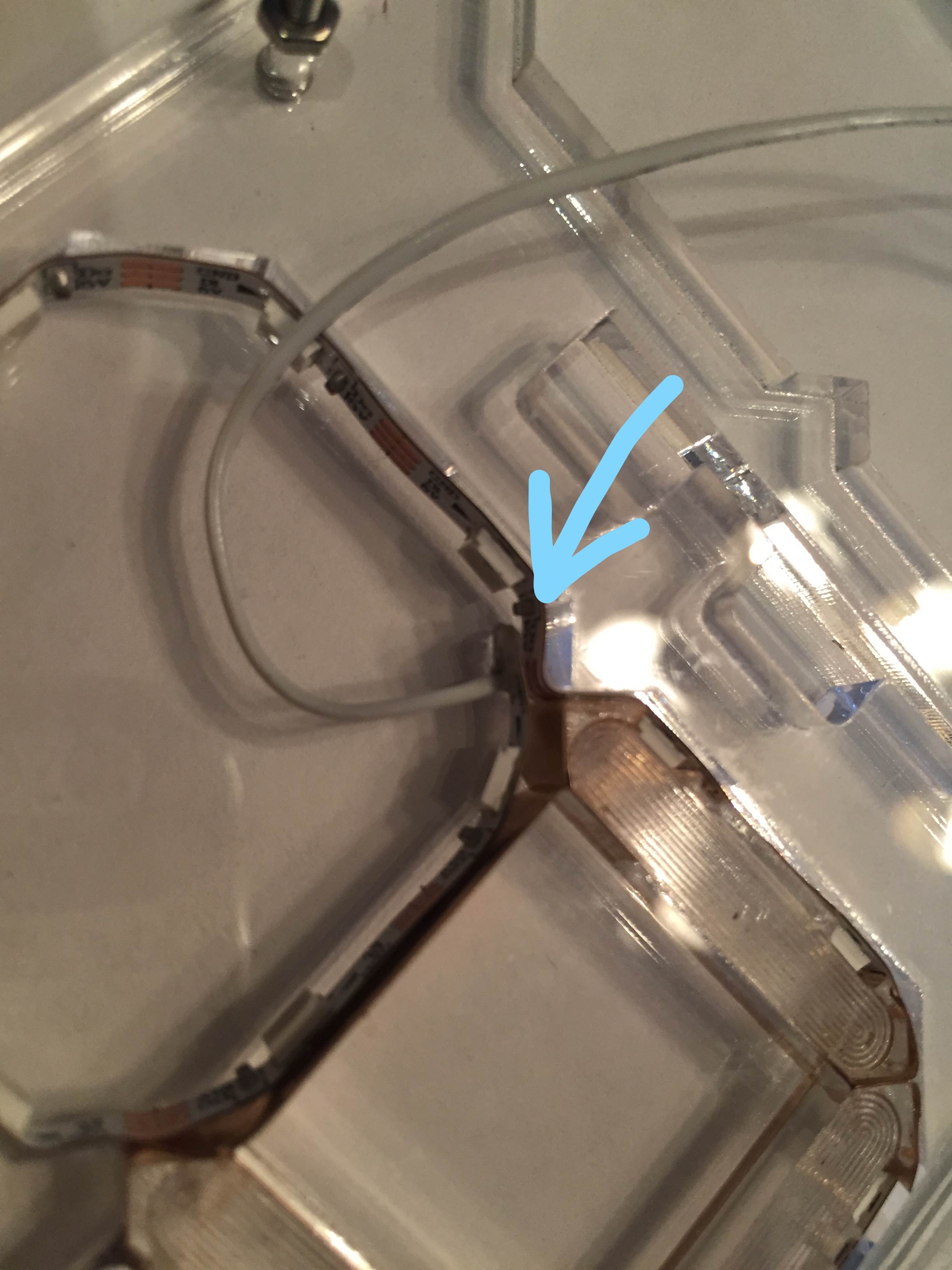
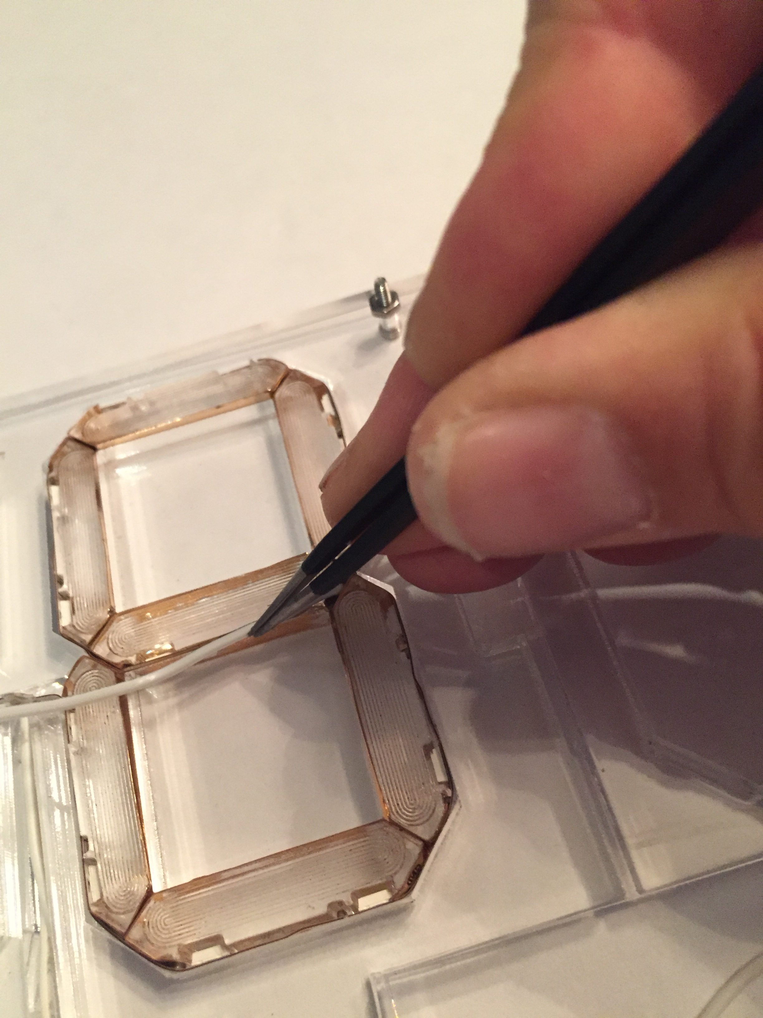
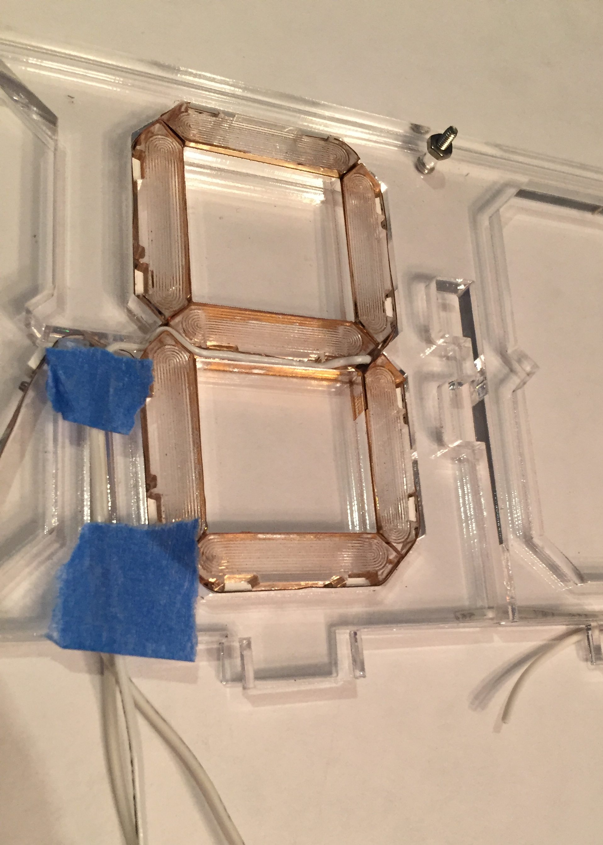
Once all the acrylic pieces are in place, we are going to carefully run the 30 AWG signal wire through the small channel between the pieces as shown below, then route it into the channel containing the power wires. I used a tweezers to gently push it into the channel, and taped the wires down with painter’s tape so that they wouldn’t pop out while assembling the other digits.
Tired yet? We still have to assemble the pieces in the left digit. The process is the same as the one we just completed, but it is slightly easier because (1) there is no signal wire on this side and (2) if you trimmed the end of the LED strip close to the capacitor, none of the solder pads in this digit will overlap (if for some reason, they do, be sure to place some very thin insulating material between them). Be sure when you place the pieces for the left digit, you run the LED strip in the mirror image pattern of the right digit, as shown in the path image with the blue arrows above.
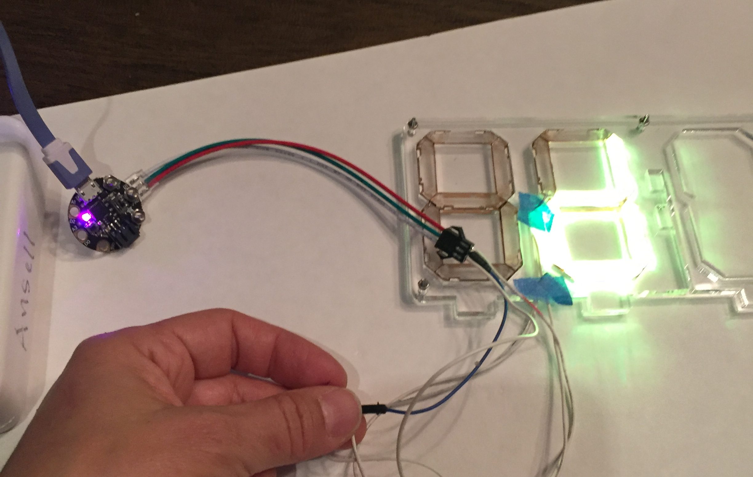
Once both digits are completely in place, connect the power signal and ground wires to the micro controller of your choice, and run a test program to make sure the LED strip is working correctly. Everything worked the first time around about 50% of the time for me. The most common problems resulted from a wire getting disconnected or pushed into contact with another solder pad.
If everything looks good, then the next step is to insert the LED strip and acrylic segments into the other digits in the display, following the exact same process again. Test each set of digits once they are done.
Step 7: Embed the LED Strip and Acrylic for the Dots
Next we’ll use short segments of the LED strip containing only two pixels to illuminate the dots in the display. There will be one or two pairs of dots, depending on whether you are building the 4 or 6 digit display. The dots are significantly easier to install than the digits.
Cut three lengths of 26 AWG hookup wire, and solder them to the input end of the 2 pixel length of LED strip. Be sure to mark the ends of each wire so that you know which is 5V, signal and GND. I used red, blue and black sharpies to color part of the insulation on each wire. Peel the adhesive backing from the LED strip and insert and stick the LED strip to the back wall of the slot with the wires hanging down the vertical channel and exiting at the bottom of the frame.
Find the small acrylic dots that fit into the frame. Cover their perimeter with vinyl foil, just as you did for the segments. Place them into their individual spaces with the etched side facing upwards and the LED and capacitor from the LED strip nestled into their respective notches.
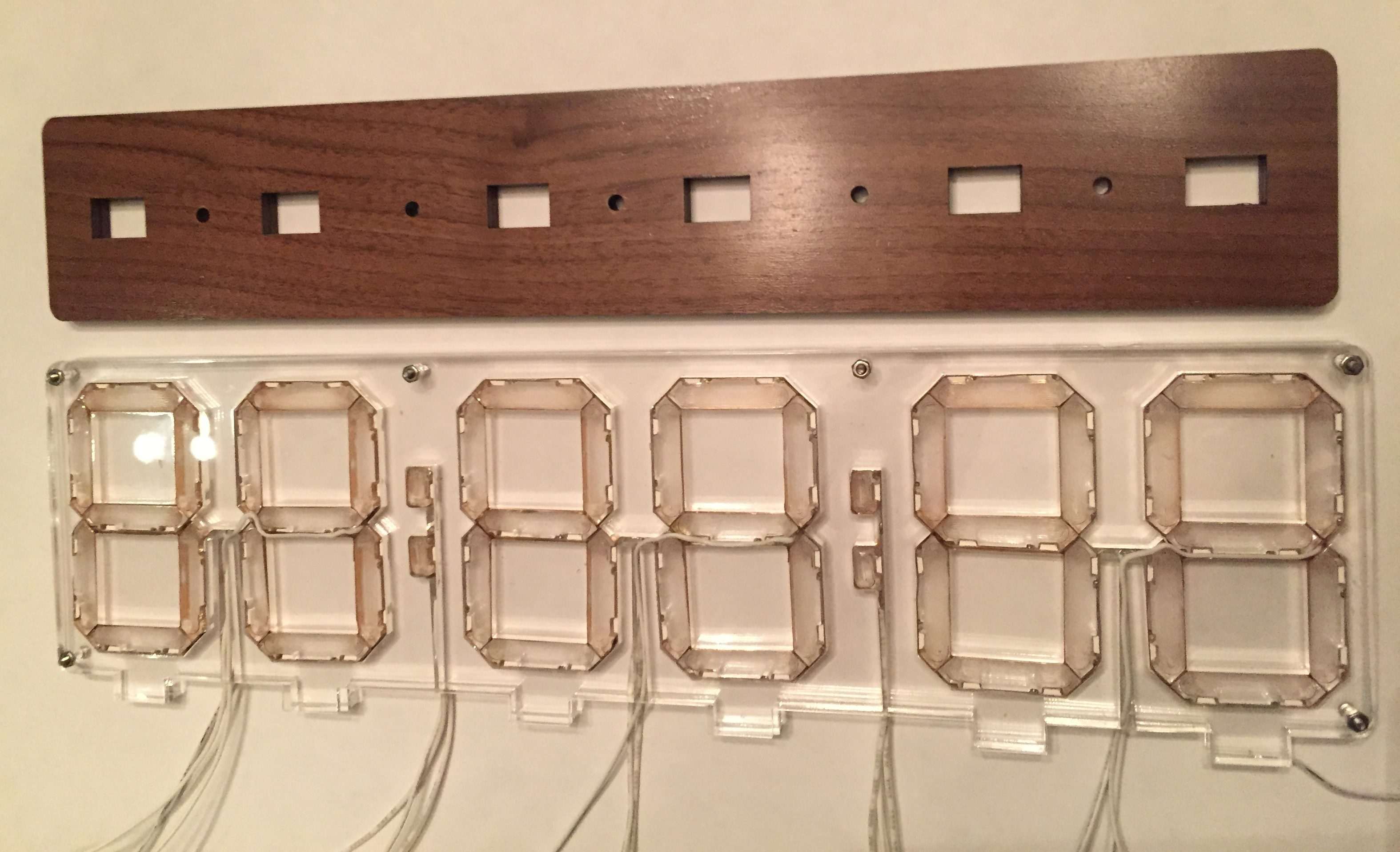
When all the dots and digits are complete, your display should look like this:
Step 8: Cover and Secure the Display
Once all the digits and dots have been assembled and all LED strips tested, we’ll place the other thin acrylic cover over them. Unscrew the nuts from the M2 screws, leaving the screws in place, and carefully remove any tape that is holding the wires in place. Carefully lower the top clear acrylic cover over the frame, slotting the screws through the holes in the cover, and taking care that all wires stay within their respective channels. When everything is in the right place, screw and tighten the nuts securely.
Step 9: Attach the Enclosure
Now we will attach the display to the lid of the enclosure. Lay the lid next to the display so that the wires line up with the holes in the lid. The lid is NOT symmetric, as the wires from the dots are not halfway between digits, so there is only one orientation in which the alignment is perfect.
Run the ends of each set of wires through their corresponding holes in the lid from the top and then carefully work the display towards the lid so that the tabs in the acrylic fit into the rectangular slots in the lid. You will probably have accomplish this in small increments. Place the ends of each wire through the holes and gently slide the lid along the wires, alternately taking up the slack in each group of wires as you go. Be very careful not to pull too hard on any one wire. Speaking from experience, it’s a major bummer to disconnect a wire at this point. Gently work the tabs into the slots. The fit is not super snug, so you will want to glue the tabs into the slots in (using JB Weld or a similar adhesive that works on both acrylic and wood) once all the electronics are connected and tested.
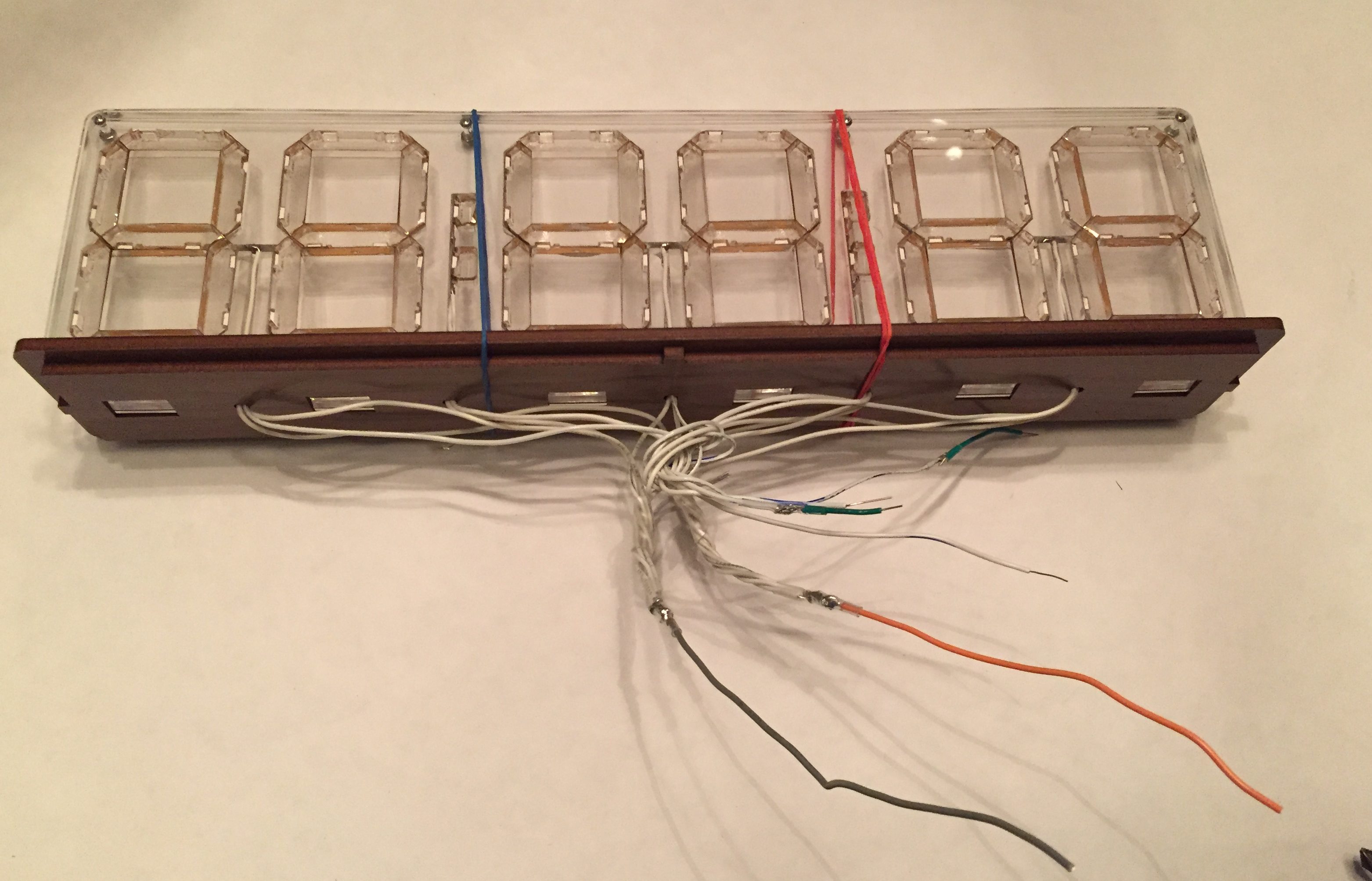
I ran a couple of rubber bands around the display and enclosure lid to keep them snugly together while I worked on the wiring. In the image above, I’ve soldered together all 5 power wires in one group and all 5 ground wires in another group, and joined each group to a single input wire, then covered all solder joints with lots of shrink tubing.
Step 10: Attach a Micro Controller (or Two)
There are many different ways to connect a controller to the display. You can solder the wires directly to your controller, but I prefer to attach connectors to the wires, leaving the flexibility to swap out micro controllers. I combined all power wires and all ground wires together, and I soldered each of the 5 signal wires to a single 5 header pin connector.
I tried out several different controllers with the edge-lit seven segment display. I like prototyping code for LED strips in CircuitPython because it’s quick and easy to get something up and running. There are a lot of pixels to control, so I opted for the Adafruit Itsy Bitsy M4 Express which is based on an ATSAMD51 board and is fast and powerful enough to control the 88 RGB LEDs in the 6-digit clock, yet small enough to fit easily in the enclosure.
The Itsy-Bitsy M4 Express worked well, but I also wanted IoT connectivity, so I tried to run the code for the display on an ESP32 board. I had problems controlling the colors in the strip while connected to the internet – similar to this issue: https://github.com/adafruit/Adafruit_NeoPixel/issues/139. The best solution was to control the LED strips from the Itsy Bitsy board and use an ESP8266 (the Lolin D1 Mini Pro) to periodically grab the correct time from the internet and send it to the Itsy Bitsy via serial communication.
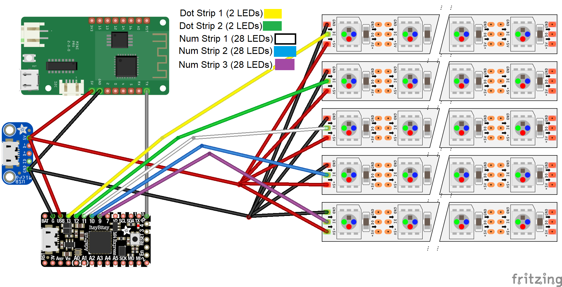
The diagram above shows wiring for the 6-digit display. To adapt it for the 4-digit display, simply omit “Dot Strip 2” and “Num Strip 3”. Since the communication between the Lolin D1 Mini and the Itsy Bitsy is one-way, it’s only necessary to connect the Lolin TX to Itsy Bitsy RX. I used a micro-USB breakout board to get 5V power input through a micro-USB cable.
Step 11: Coding the Display
The display is coded as a clock, but there is a lot of additional potential additional functionality. It could be a countdown timer, a temperature display, a social media follower count display, or basically a display of any metric that can be represented in numbers.
Disclaimer: the code provided below is somewhat hacky and not incredibly well documented. It works, but could be significantly improved. I hope to find time to improve and update it, but for now, I’m putting out what I have, because I’m not sure when I’ll be able to improve it.
I programmed the Lolin D1 Mini Pro with the Arduino IDE. The code, shown below, connects to the internet, and uses the “NTPClient” library (available through the Arduino library manager) to obtain the correct time. The NTPClient object reads the time from the NTP server every 10 minutes. It formats and sends a time string over the serial port every 10 seconds.
#include <Adafruit_NeoPixel.h>
#include <ESP8266WiFi.h>
#include <NTPClient.h>
#include <WiFiUdp.h>


/* OTA Time Access via WiFi */
const char* ssid      = "YOUR SSID HERE";
const char* password  = "YOUR PASSWORD HERE";

char timeString[8];
// Define NTP Client to get time
WiFiUDP ntpUDP;
NTPClient timeClient(ntpUDP);
/* End OTA Time Access via WiFi */

void setup() {
  Serial.begin(57600);

  // Initialize WiFi Connection
  //  Serial.print("Connecting to ");
  //  Serial.println(ssid);
  WiFi.begin(ssid, password);
  while (WiFi.status() != WL_CONNECTED) {
    delay(200);
//    Serial.print(".");
  }
  delay(200);
  // Print local IP address and start web server
  //  Serial.println("");
  //  Serial.println("WiFi connected.");
  //  Serial.println("IP address: ");
  //  Serial.println(WiFi.localIP());
  //  IPAddress ip = WiFi.localIP();


// Initialize a NTPClient to get time
  timeClient.begin();
  // Set offset time in seconds to adjust for your timezone, for example:
  // GMT +1 = 3600
  // GMT +8 = 28800
  // GMT -1 = -3600
  // GMT 0 = 0
  timeClient.setTimeOffset(-25200);  // GMT-7
  timeClient.setUpdateInterval(600*1000);  // in Milliseconds. We update every 10 min

}

void printTimeSerial() {
    sprintf(timeString, "%02d:%02d:%02d", timeClient.getHours(), timeClient.getMinutes(), timeClient.getSeconds());
    Serial.println(timeString);
}

boolean sendTime = true;
int lastSec;
void loop() {
  // Send time every 10 seconds when transitioning from seconds = 4 to seconds = 5
  timeClient.update();
  int sec = timeClient.getSeconds() % 10;
  if (sec == 5 and lastSec == 4) {
    printTimeSerial();
  }
  lastSec = sec;
}
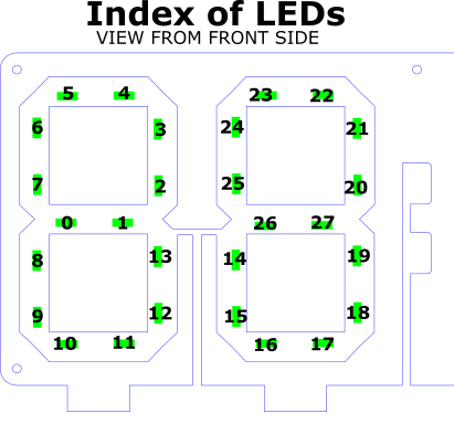
Due to the way the LED strip is laid out, the order of the LEDs in the adjacent digits in each pair is different. The first LEDs in the strip illuminate the left (higher place value) digit, and the second half of the strip illuminates the right (lower place value) digit. The code takes this into account with an offset of 14 pixels for the rightmost digit. Each pair of digits is coded the same way, so code-wise you could easily extend this display to 8, 10 or any even number of digits.
The Circuit Python code running on the Itsy Bitsy polls the serial port to read the time strings sent from the ESP8266. It sets a new base time with every new time string it receives, then tracks the current time using the monotonic() function from the time library.
The code uses the adafruit_fancyled library to chose colors in HSV format and apply gamma correction before they are displayed. The color of the numbers evolves over a 60-second cycle that restarts at the top of every minute.
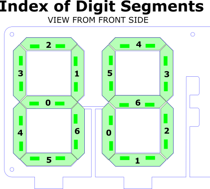
The indices of the segments required to display any given number on the LEDs are stored as bits in the array digitSegments, and unpacked in the function drawStripDigit.
import board
import neopixel
import time
import random
import busio
import adafruit_fancyled.adafruit_fancyled as fancy

uart = busio.UART(board.TX, board.RX, baudrate = 57600, timeout=50)

#DEFINE THE NUMBER OF DIGITS IN THE DISPLAY HERE:
NDIGITS = 6

NDOTS = NDIGITS//2 - 1

NPIX_PER_STRIP = 28
NPIX_PER_DIGIT = NPIX_PER_STRIP//2

#ADJUST THIS VALUE TO CHANGE THE BRIGHTNESS
BRIGHTVAL=.6

DIGIT_LEFT = 1
DIGIT_RIGHT = 2
DIGIT_BOTH = DIGIT_RIGHT | DIGIT_LEFT

dot_strips = [neopixel.NeoPixel(board.D13, NDOTS, auto_write=False)]
if NDIGITS == 6:
	dot_strips = dot_strips + [neopixel.NeoPixel(board.D12, NDOTS, auto_write=False)]

num_strips = [neopixel.NeoPixel(board.D9, NPIX_PER_STRIP, auto_write=False),
			  neopixel.NeoPixel(board.D10, NPIX_PER_STRIP,  auto_write=False)]
if NDIGITS == 6:
	num_strips = num_strips + [neopixel.NeoPixel(board.D11, NPIX_PER_STRIP, auto_write=False)]
all_strips = dot_strips + num_strips


#Bits (written as decimal) corresponding to the digits 0-9 for both left and right digit display
digitSegments = [[126,66,55,103,75,109,125,70,127,79],[63,12,91,94,108,118,119,28,127,124]];
#Defines the segments in each digit which form a circle
circleLeds = [[2,3,4,5,6,7,8,9,10,11,12,13],[20,21,22,23,24,25,14,15,16,17,18,19]]

def showAll():
    for i in range(len(all_strips)):
        all_strips[i].show()

def clearAll():
    for i in range(len(all_strips)):
        all_strips[i].fill((0,0,0))
    showAll()

#lights up the correct LEDs in the segment
def segment(strip, index, seg, col):
    led_offset = index*NPIX_PER_DIGIT  #will be 0 or 14
    strip[seg*2+led_offset] = col
    strip[seg*2+led_offset+1] = col

def fillDots(col):
    dots1.fill(col)
    dots2.fill(col)

#DRAWS A CIRCLE PATTERN ON ALL DIGITS
firstIndex = 0
def circle(position, digit = DIGIT_BOTH, reps=48,trailLength=4):
    strip = num_strips[position]
    global firstIndex
    global gHue
    hueIncrement = .02
    nLeds = len(circleLeds[0])
    for rep in range(reps):
        gHue = gHue + hueIncrement
        bright = 1.0
        for i in range(0,trailLength,1):
            col = fancy.gamma_adjust(fancy.CHSV(gHue+i*hueIncrement, 1.0, bright)).pack()
            if (digit & DIGIT_LEFT):
                strip[circleLeds[0][(firstIndex+i)%nLeds]] = col
            if (digit & DIGIT_RIGHT):
                strip[circleLeds[1][(firstIndex+i)%nLeds]] =col
            bright = bright*.75

        if (digit & DIGIT_LEFT):
            strip[circleLeds[0][(firstIndex+trailLength)%nLeds]] = (0,0,0)
        if (digit & DIGIT_RIGHT):
            strip[circleLeds[1][(firstIndex+trailLength)%nLeds]] = (0,0,0)
        strip.show()
        firstIndex = firstIndex - 1
        if firstIndex < 0:
            firstIndex = len(circleLeds[0]) - 1


def clearDigit(position, doShow=True):
    strip = num_strips[position//2]
    offset = position % 2
    first = offset * NPIX_PER_DIGIT
    last = first + NPIX_PER_DIGIT
    strip[first:last]=[(0,0,0)]*NPIX_PER_DIGIT
    if doShow:
        strip.show()

#Translates drawing digits to lighting up the correct segments
def drawStripDigit(strip, offset, segValues, col):
    mask = 1
    for i in range(7):
        if (segValues & mask):
            segment(strip, offset, i, col)
        else:
            segment(strip, offset, i, (0,0,0))
        mask <<=  1

def drawDigit(position, value, col,doShow=False):
    offset = position % 2
    strip = num_strips[position//2]
    segValues = digitSegments[offset][value]
    drawStripDigit(strip, offset, segValues, col)
    if doShow:
        strip.show()

#Draws a 2-digit number on the specified "set" of digits in the display
def drawNumber(setIndex, value, col, doShow=False, drawLeadingZero=True):
    strip = num_strips[setIndex]
    if (drawLeadingZero or value >= 10):
        lValues = digitSegments[0][value // 10]
        drawStripDigit(strip, 0, lValues, col)
    else:
        clearDigit(setIndex*2)
    rValues = digitSegments[1][value % 10]
    drawStripDigit(strip, 1, rValues, col)
    if doShow:
        strip.show()


gHue = 0
hueInc = 0.003

lastUpdateTime = 0
timeHr = 0
timeMin = 0
timeSec = 0
baseSec = 0
baseMin = 0
baseHr = 0

def updateTime():
    global timeSec, timeMin, timeHr
    global baseSec, baseMin, baseHr
    elapsedSec = int(time.monotonic() - lastUpdateTime)
    totSec = elapsedSec + baseSec
    timeSec = totSec % 60
    timeMin = ((totSec // 60) + baseMin) % 60
    timeHr = ((totSec // 3600) + baseHr) % 24

def getUartTimeData():
    global lastUpdateTime, baseHr, baseMin, baseSec
    data = uart.read(32)
    result = False
    if data is not None:
        #convert bytearray to string
        try:
            data_string = ''.join([chr(b) for b in data])
            #print(data_string, end="")
            hr = int(data_string[0:2])
            min = int(data_string[3:5])
            sec = int(data_string[6:8])
            lastUpdateTime = time.monotonic()
            baseHr = hr
            baseMin = min
            baseSec = sec
            result = True
        except:
            print(data_string)

    return result


def onStart():
    while not getUartTimeData():
        for pos in range(NDIGITS/2):
            circle(pos, DIGIT_BOTH, 1)
        time.sleep(.05)

onStart()

while True:
    if lastUpdateTime:
        updateTime()

    gHue = timeSec/60.0
    col = fancy.gamma_adjust(fancy.CHSV(gHue, 1.0, BRIGHTVAL)).pack()
    drawNumber(0, timeHr, col, drawLeadingZero=False)
    drawNumber(1, timeMin, col)
    if NDIGITS == 6:
		drawNumber(2, timeSec, col)
    index = timeSec % 2
	if NDIGITS == 6:
		dot_strips[index].fill(col)
		dot_strips[1-index].fill((0,0,0))
	elif NDIGITS == 4:
		dot_strips[0][index] = col
		dot_strips[0][1-index] = (0,0,0)
    showAll()

    getUartTimeData()
I hope to clean up and update this code at some point later – but I’m putting it up now, warts and all, in case anyone would like to use it in the meantime.
Step 12: Whew!
If you’ve made it this far, good for you! I hope you enjoy this project. It was a lot of work, but quite rewarding to make.
Wow! I started a 7-segment led project last year but this blows it away.
how can i get in contact with builder of this project, the contactform is not working.
Have 2 questions.
1. Is the second *.ino for the Itsy? and hoe to define the : #DEFINE THE NUMBER OF DIGITS IN THE DISPLAY HERE:
and : #ADJUST THIS VALUE TO CHANGE THE BRIGHTNESS
2. Or must i combine the 2 programs togeher.