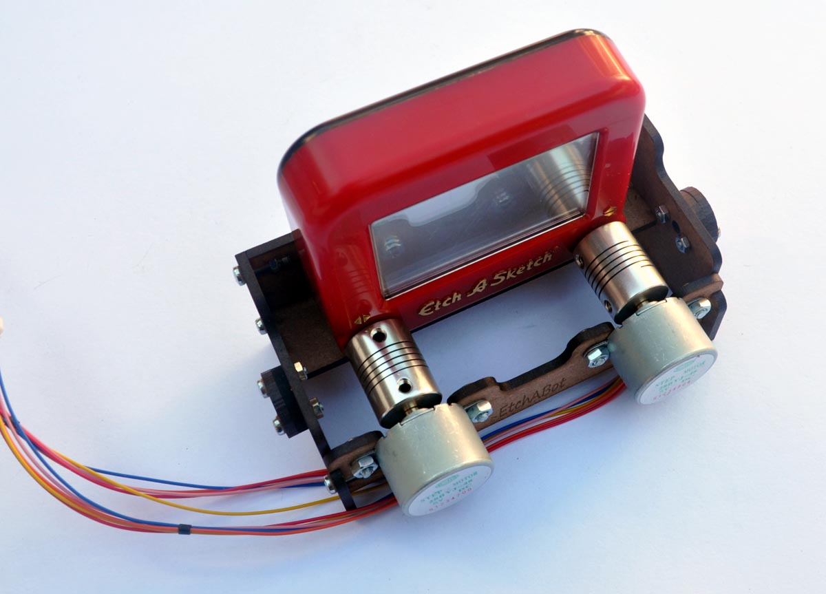
EtchABot turns your Etch A Sketch into a CNC (Computer Numerical Control) drawing machine. I’m really excited about this project because of its versatility and its well balanced combination of entertaining and educational aspects. It’s always fun to hack a toy to do something above and beyond its original intent, and if you build the EtchABot and run the example Arduino sketches, you can make:
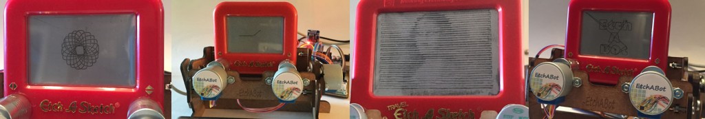
- A self-erasing Spirograph
- An analog clock
- A joystick-controlled doodling machine
- A web browser-controlled drawing robot to reproduce free-hand, raster or SVG digital images.
There is an EtchABot Arduino library, so it’s also easy to program it with your own ideas.
Other makers have used stepper motors to turn an Etch A Sketch into a simple CNC machine that can draw portraits, patterns and even tell digital time. Each of these previous builds have been one-offs with unique methods to attach motors to an Etch A Sketch. They are terrific projects, but difficult to replicate. What’s original about the EtchABot is its easy-to-build frame and the Arduino library provided to control it. There is no glue, cutting, drilling or soldering required. Anyone with a basic knowledge of breadboard wiring and Arduino programming can construct and run it.
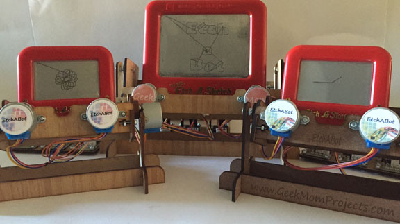
Etch-a-Bot can sit on your desk and display your pictures to the world. Or use the Etch-a-Bot Arduino library as a basis to create your own original project.
Licensing:

EtchABot by Debra Ansell (GeekMomProjects) is licensed under a Creative Commons Attribution-NonCommercial-ShareAlike 4.0 International License.
If you would like to make an EtchABot for your own use, please feel free to follow the instructions, obtain your own parts and modify the hardware/software however you would like. For those who would prefer to purchase a kit to make one, I have a small number for sale on tindie: https://www.tindie.com/products/geekmomprojects/etchabot/. I do ask that you not sell the EtchABot or kits to make one. If you’d like to put together an EtchABot as a project for your makerspace or school, then more power to you. If you are in the Los Angeles area and would like me to run an EtchABot workshop, please reach me through the Contact page on this site.
Table of contents:
Getting started:
You can build an EtchABot with either the pocket size (small) or the travel size (medium) Etch A Sketch. The only mechanical difference between the two versions is the size and scaling of the wooden frame. The pocket size frame is somewhat more stable and easier to rotate due to its lighter weight. Otherwise, the assembly instructions are identical. If you purchase a kit, the only additional parts you will need to get are the Arduino and the Etch A Sketch.
Please be aware that you will need to modify the Arduino sketches to specify the size of the Etch A Sketch before uploading them. Otherwise you can damage your Etch A Sketch by trying to run its stylus past the edges. The default code settings for the sketches are for the pocket size Etch A Sketch. You’ll see where to modify the code to specify the size later on in these instructions.
Components:
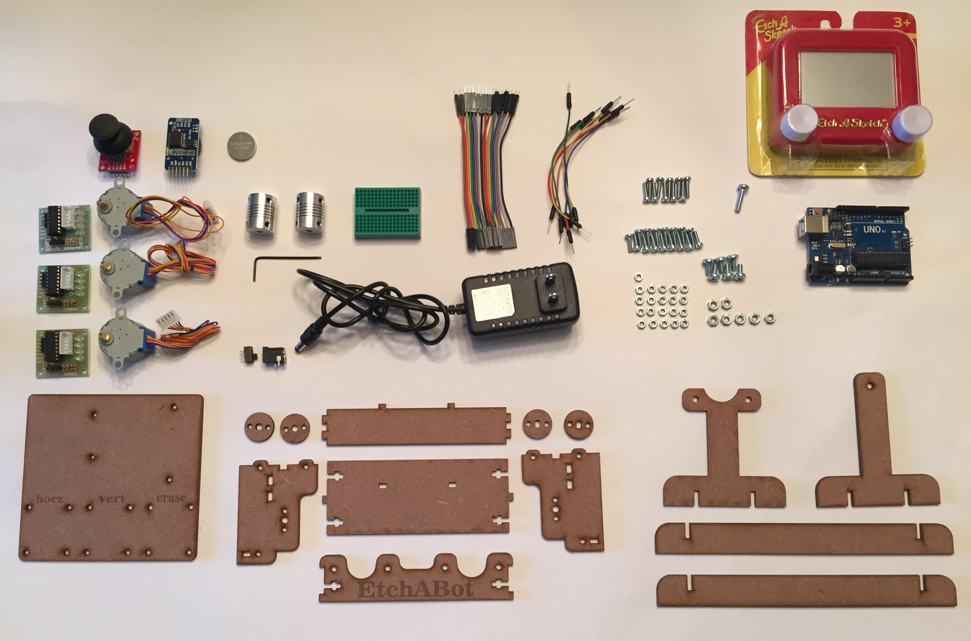
- Etch a Sketch, Pocket(shown) or Travel size x 1 [Ohio Art](I strongly recommend getting this directly from the original manufacturer, Ohio Art. I’ve found that the erasing mechanism is of better quality than the knockoffs you may find online.)
- 28BYJ-48 stepper motors x 3 [EBay] (These must have approximately 64:1 gearing ratio. Most do, but some models out there have a 16:1 ratio, so be careful if you purchase these yourself) Also, it’s best to use three motors from the same manufacturer as I found out the hard way that some manufacturers wire them differently than others.
- ULN2003 stepper motor drivers x 3 (these often come pre-packaged with the 28BYJ-48 stepper motors).
- Laser cut wooden parts (see below for laser cutter files) from 1/8″ MDF or similar wood. Make sure you get the right size wooden parts to correspond to the size of Etch A Sketch you are using (pocket size or travel size).
- Screws and Nuts [McMaster-Carr]:
- M3 12mm Machine Screws x 10
- M3 10mm Machine Screws x 16
- M3 Hex Nuts x 26
- M4 16mm Machine Screw x 1
- M4 8mm Machine Screws x 6
- M4 Hex Nuts x 7
- 5mm to 5mm Flexible shaft couplers x 2 [EBay] Get the kind that tightens with 4 set screws. You will need a 2mm allen key to tighten the set screws in the metal shaft couplers.
- Arduino Uno (easiest), Nano or other compatible board x 1 [Arduino], and USB cable to connect it to your computer for programming
- Breadboard wires– Male to Female x 18 and Male to Male x 5 (approx) [EBay]. The 10 cm length look neater when they’re all wired up, but you can use any length
- 6V 1A power adapter x 1 [EBay]
- Barrel jack to breadboard connector [Sparkfun]
- 170 tie-point breadboard x 1 [Sparkfun] (used to connect power from the adapter to the electronics – you could solder together your own connector if you prefer)
- Breadboard compatible slide switch x 1 [Sparkfun] (optional, but it makes turning the EtchABot on/off much easier than disconnecting the power cable each time)
- Optional components:
EtchABot Assembly:
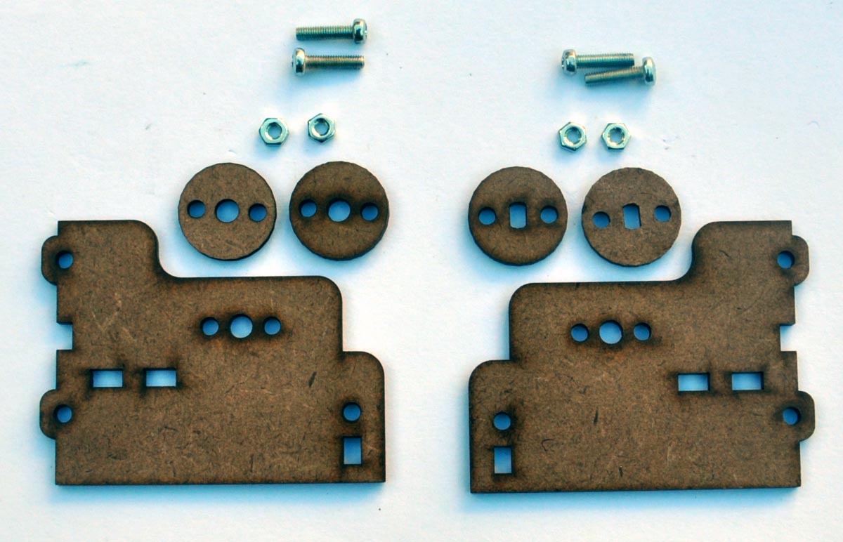
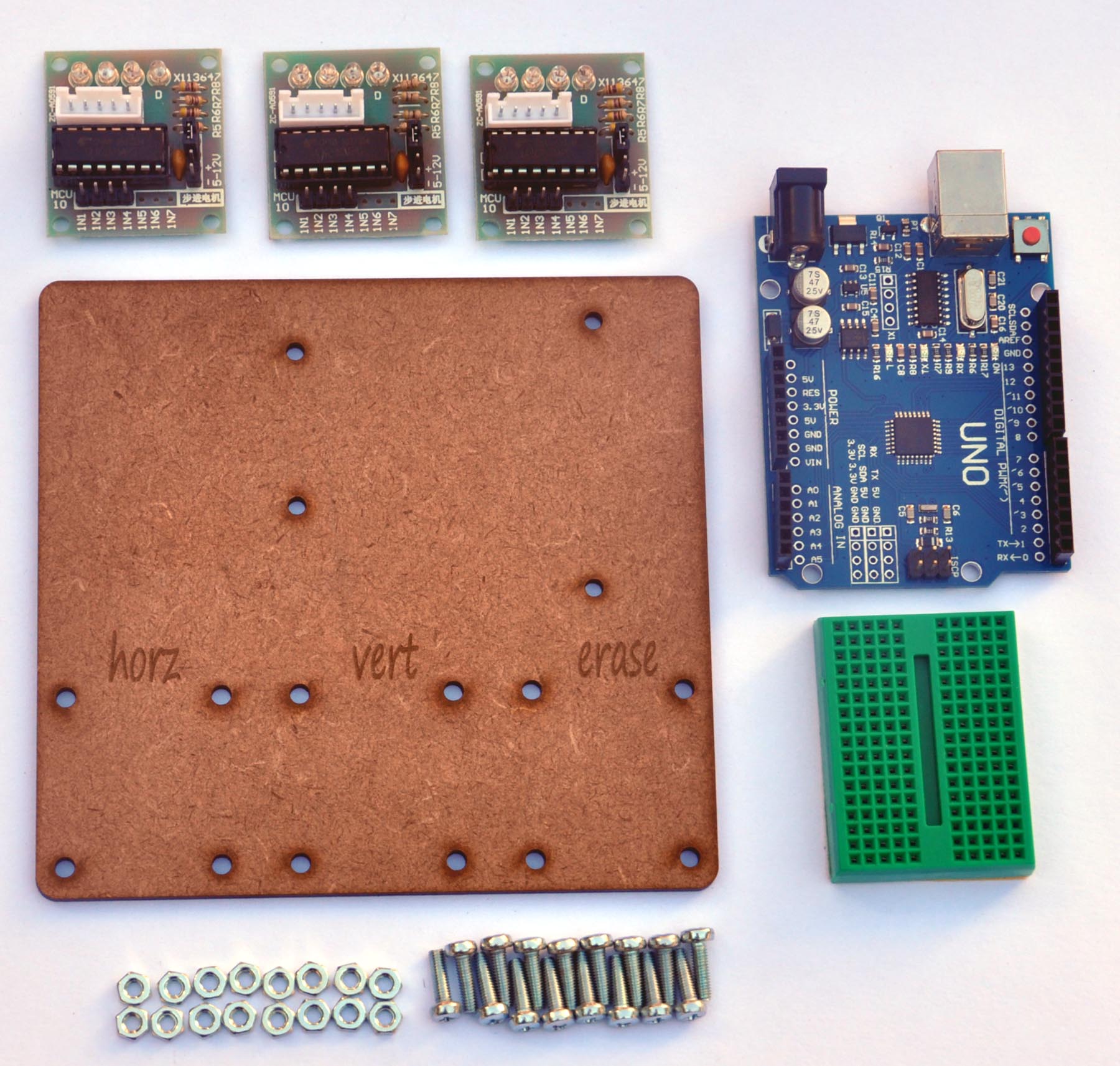
Step 1: Gather the laser-cut parts
The wooden parts are included in the kit, or, if you are cutting your own parts, go to GitHub for CAD files in SVG format. Black lines in the file are for cutting, and red lines are for etching. The parts are designed to be cut from 1/8″ MDF (approx. 3.2 mm) or any comparable wood. The frame will be difficult to put together if your wood is a different thickness .
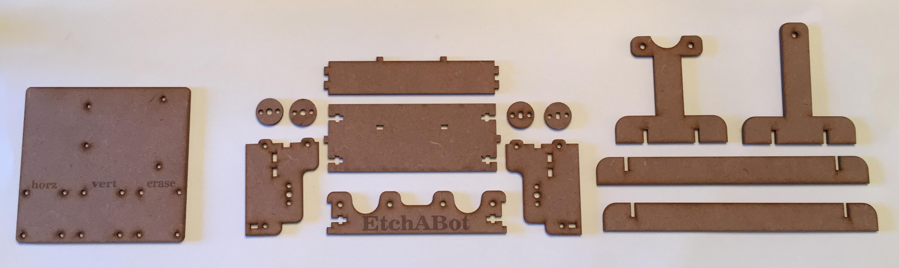
The assembly steps are the same whether you are using the Pocket or Travel size Etch A Sketch. First, lay out and identify all of the parts. The EtchABot frame has three major components: the body (which holds the Etch A Sketch), the base (which hold the body and allow it to rotate), and the electronics board (which organizes the electronics).
Personalization Tips:

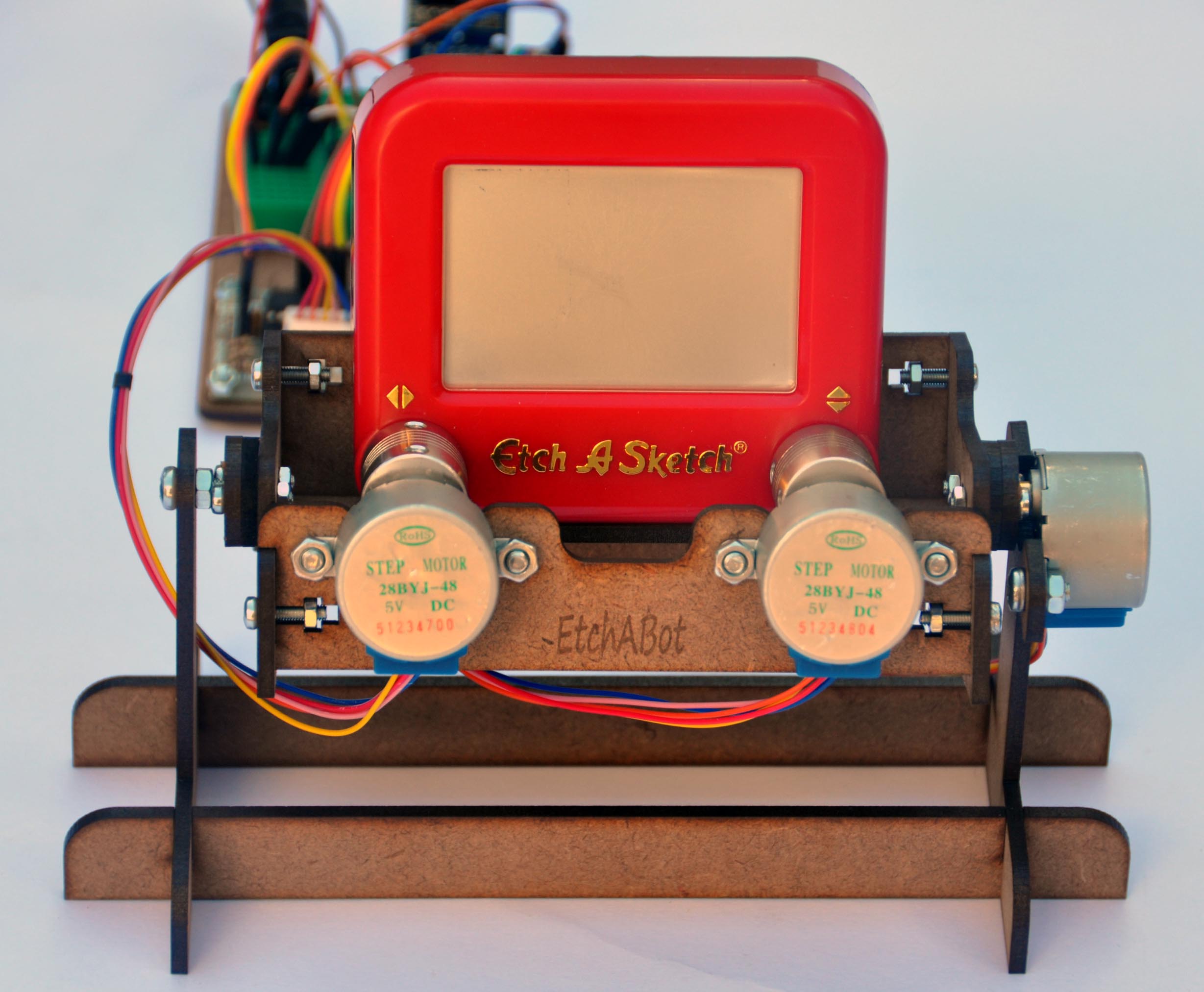
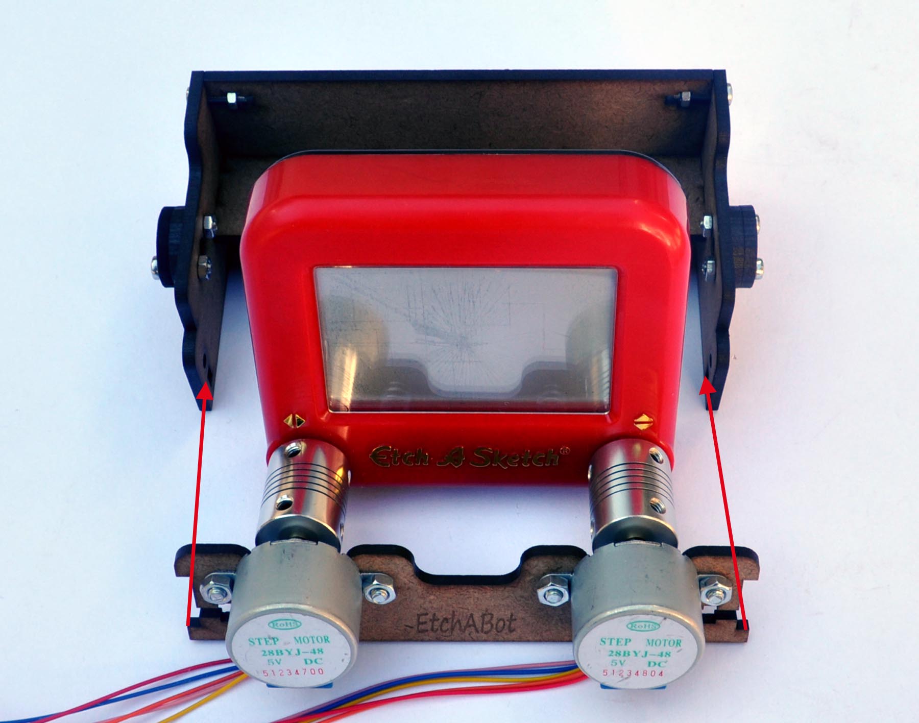
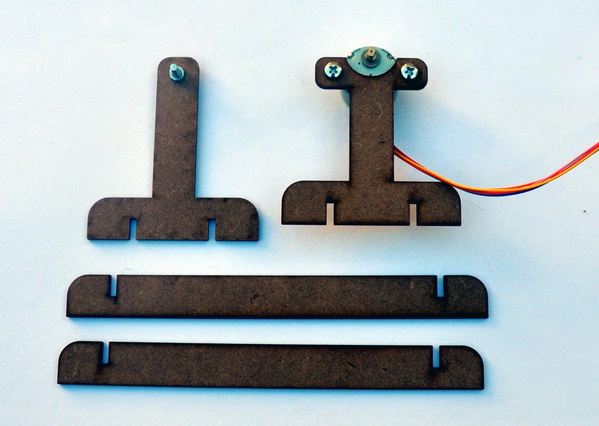
Step 2: Attach stepper motors and M4 16mm screw to wood frame
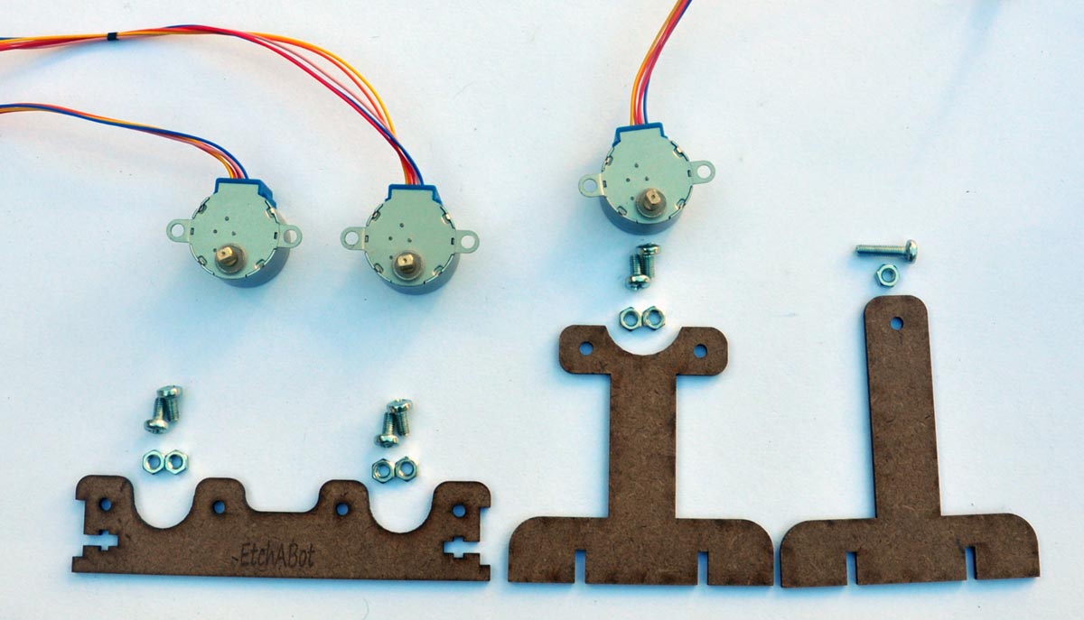
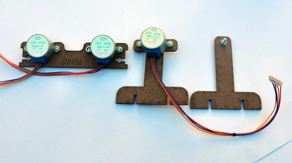
Screw the motors into the front wooden panel and the right side support as shown in the pictures above using all 6 of the 8mm M4 screws. Screw the 16mm M4 screw into the left side support as shown.
Step 3: Assemble the back and sides of the body
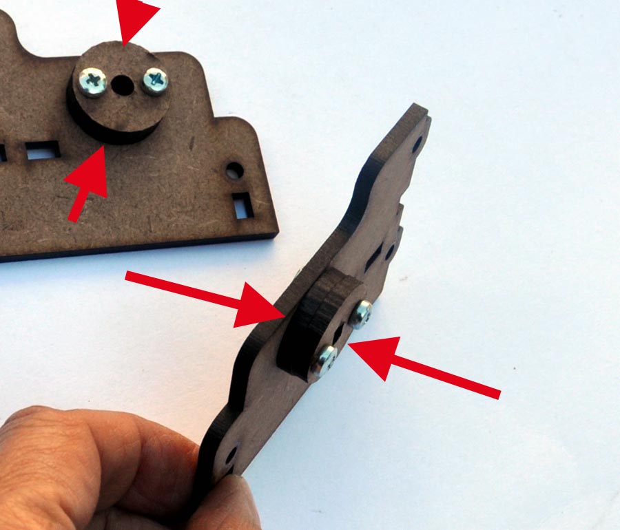
Align and stack two circular axle hubs on each side panel and attach them to the side panels of the body with the M3 12mm screws as in the pictures below. The axle hubs with the circular center hole attach to the left side panel and the axle hubs with the flattened center hole attach to the right side panel, as shown in the images below.
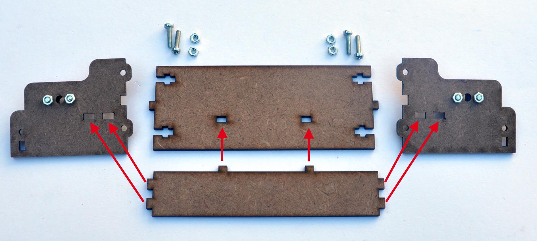
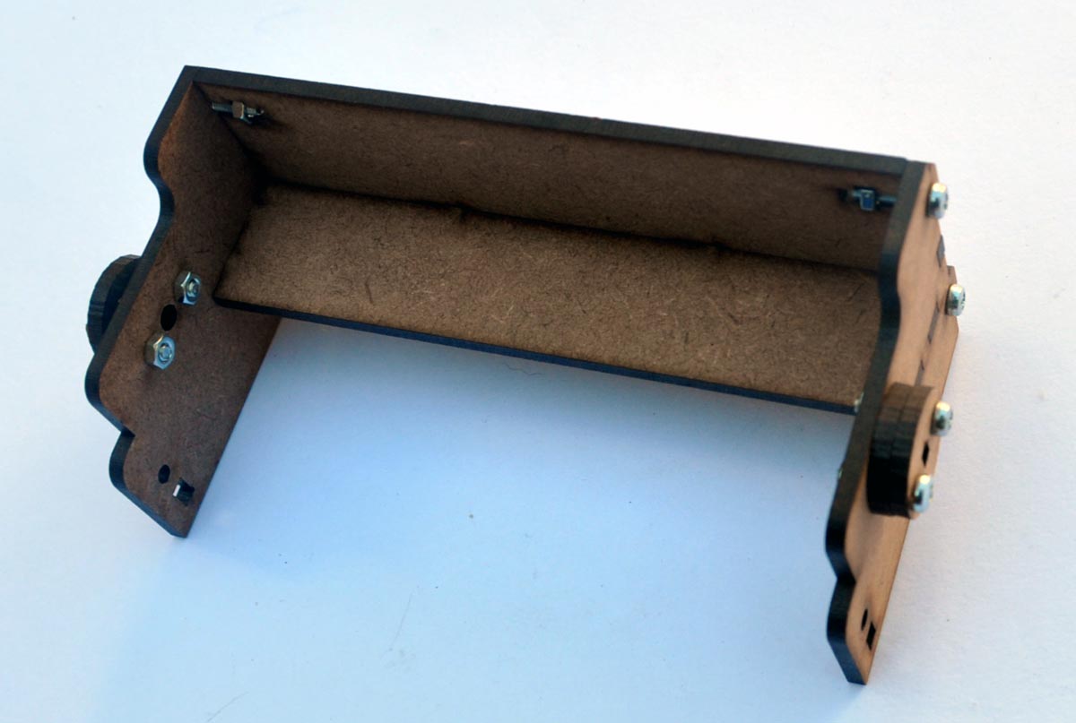
Next connect the sides, back and bottom of the EtchABot body togeher. Slide the tabs on the back and bottom into the slots in the side panels as in the picture below. Hold the pieces gently together while using 4 of the M3 12mm screws to secure the back and side panels to the body as shown below.
Step 4: Connect the shaft couplers to the Etch A Sketch
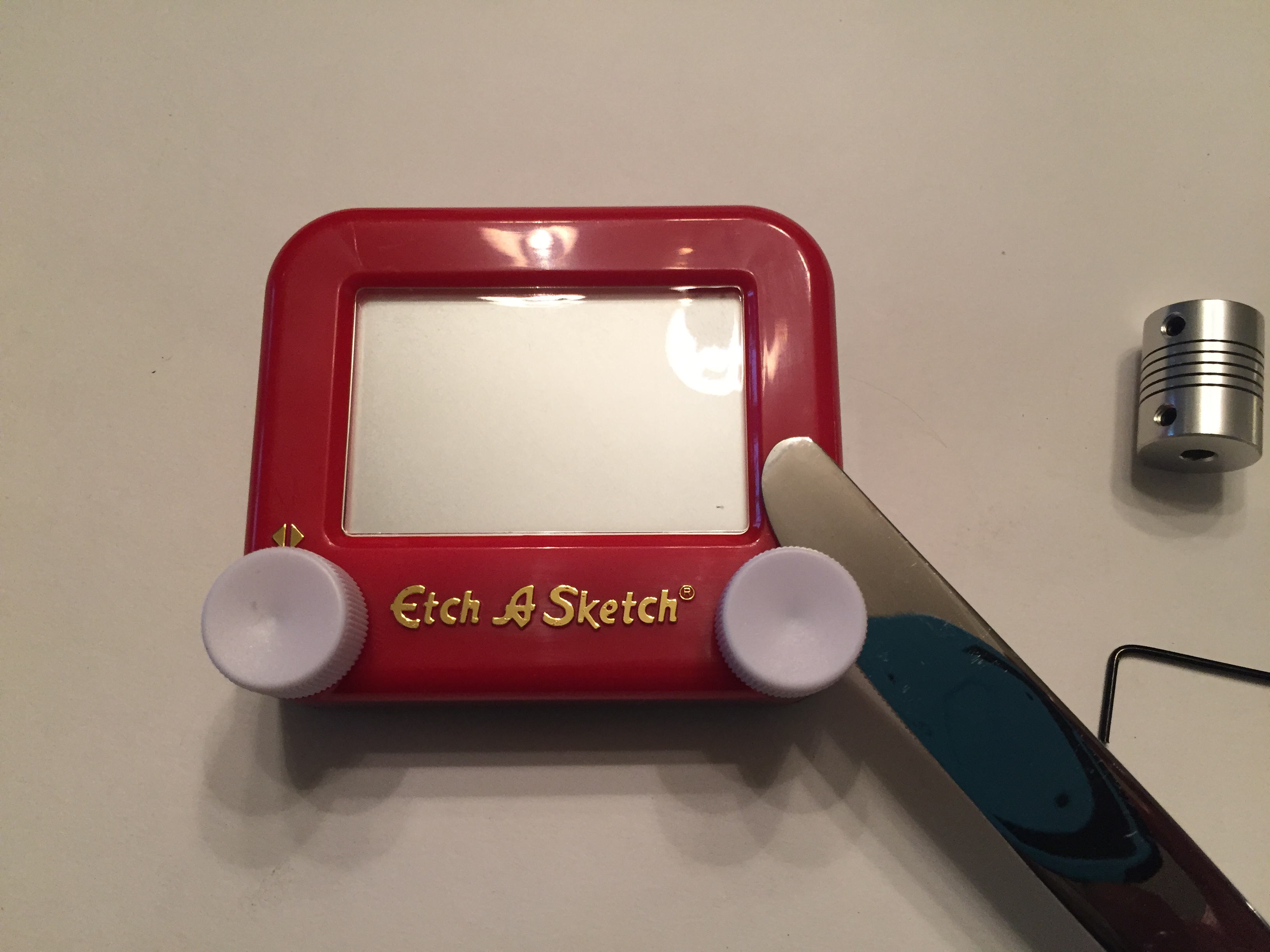
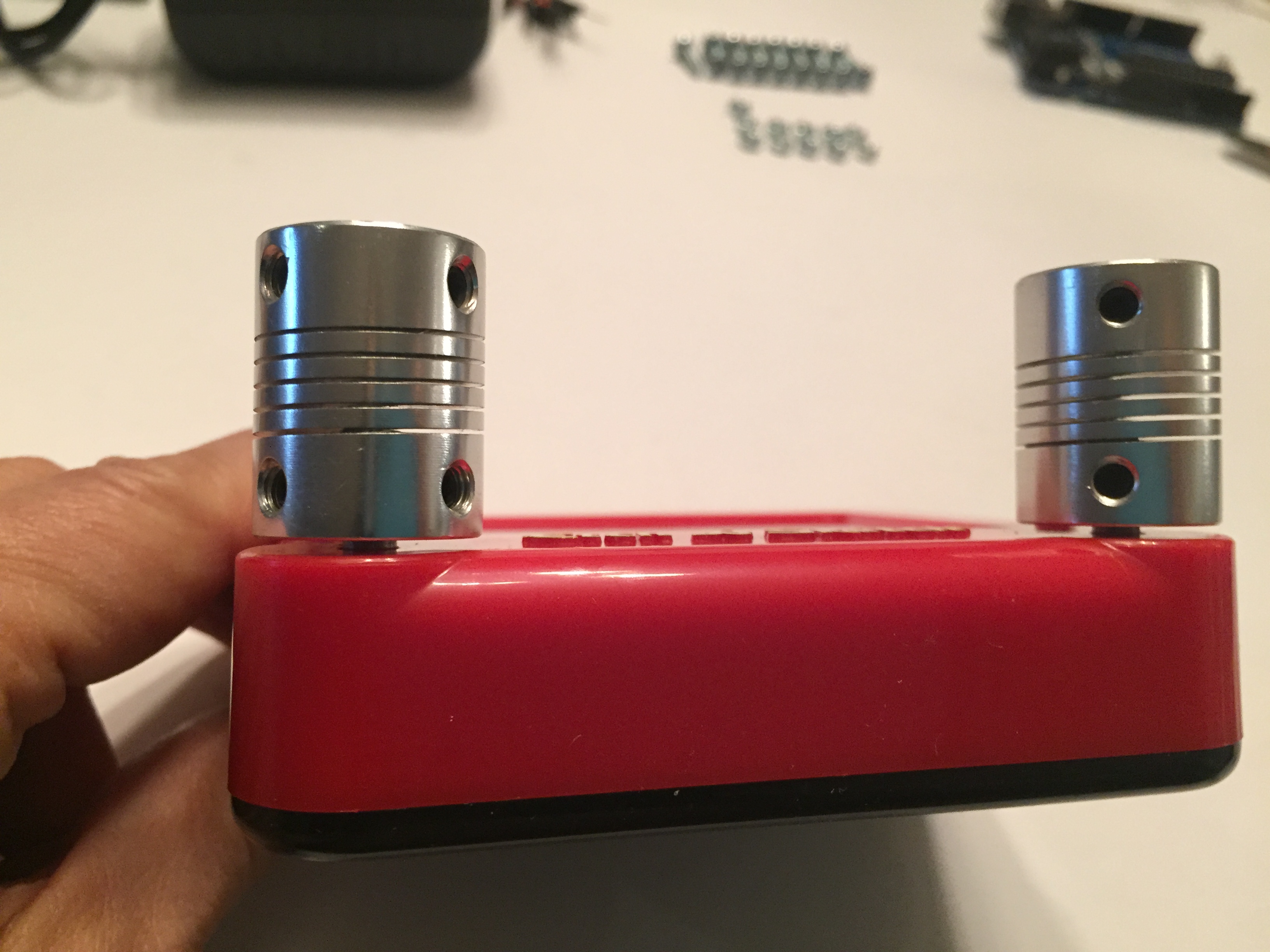
First, remove the knobs from the Etch A Sketch. They can be pulled of with gentle force, or pried off with the edge of a butter knife. Then attach the shaft couplers to the Etch A Sketch shafts where the knobs were. There should only be a millimeter or two of clearance between the Etch A Sketch frame and the edge of the shaft coupler (see picture above). Tighten the set screws with the 2mm allen key until the shaft couplers are secure.
Step 5: Attach the shaft couplers to the stepper motors
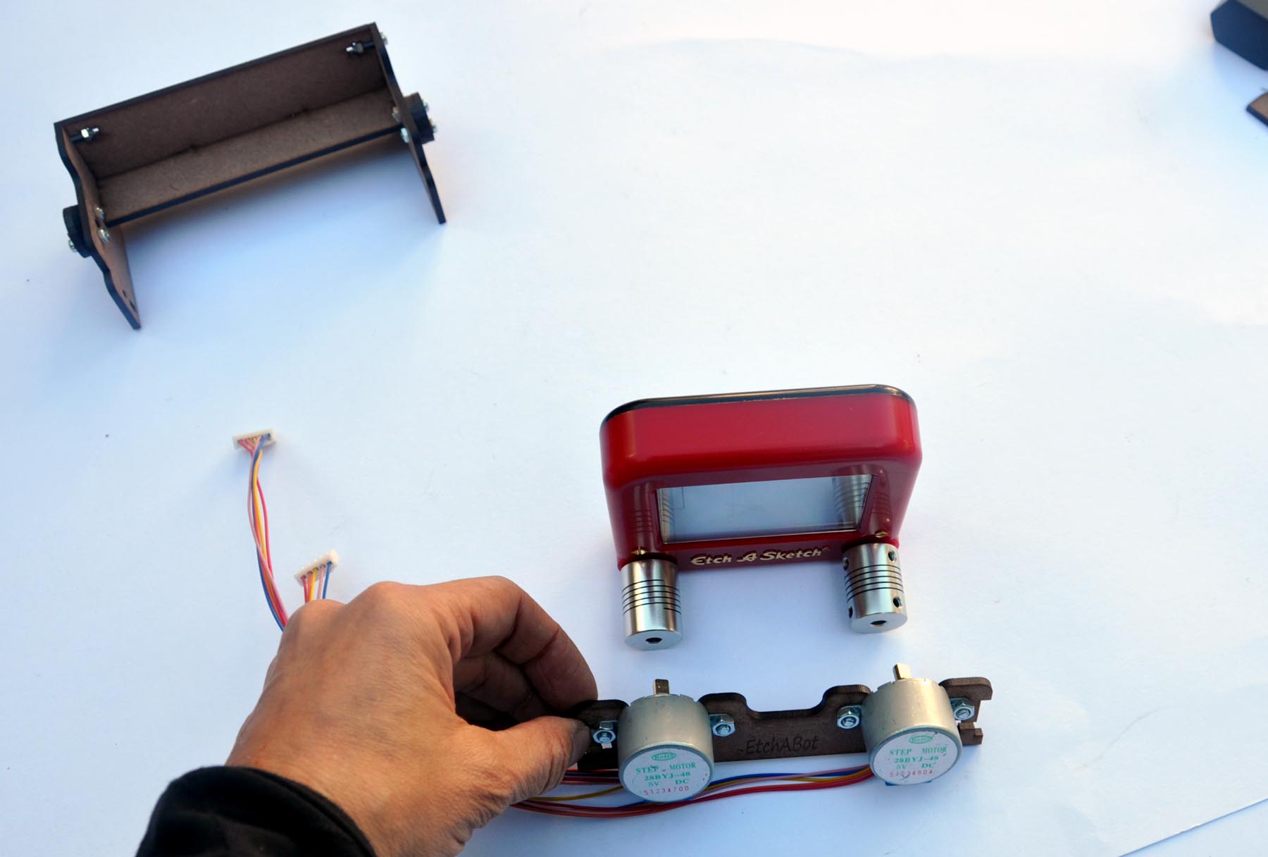
Slide the front panel containing the two stepper motors towards the Etch A Sketch until the stepper motor shafts go in the holes of the shaft couplers. Slide the motor shafts into the couplers until only a millimeter or two of clearance exists between the motor body and the shaft coupler. Once they are in place, tighten the set screws securely with the 2mm allen key.
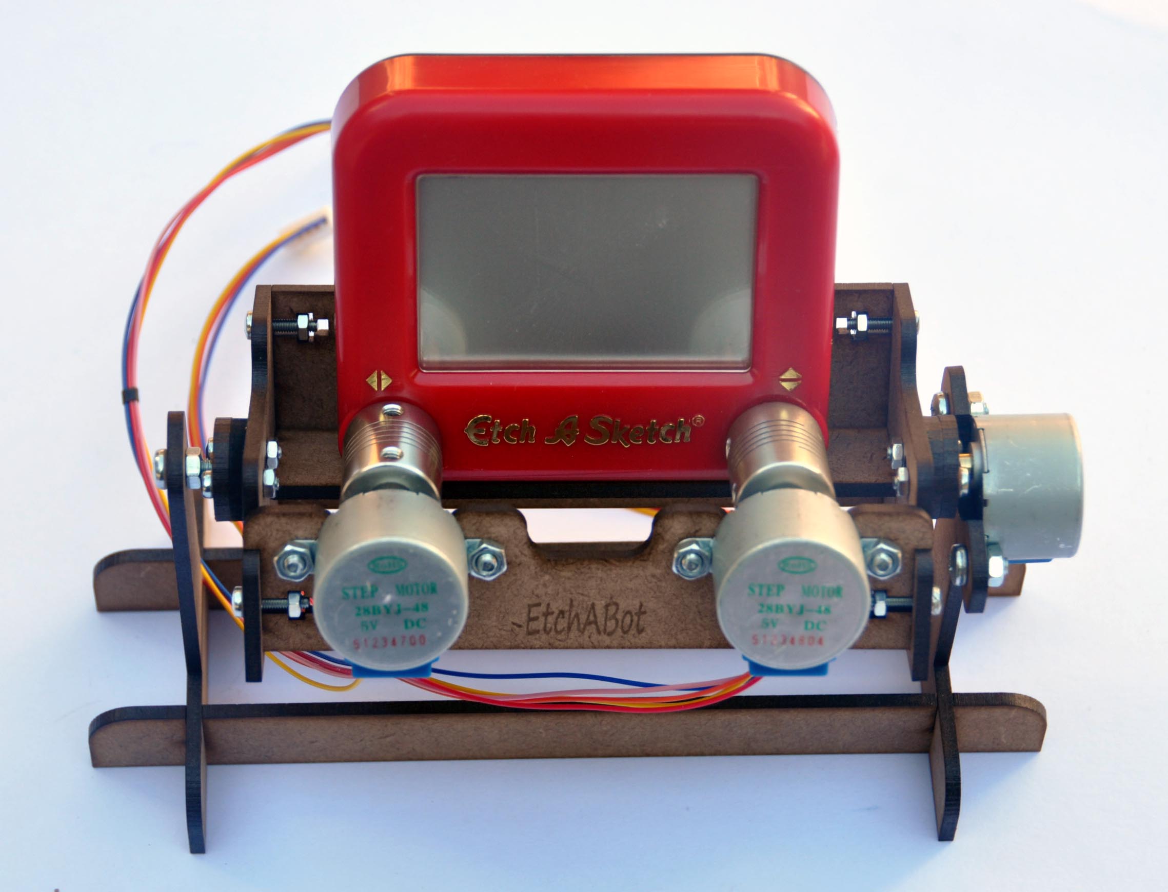
Step 6: Attach the front panel
Gently separate the side panels of the EtchABot body just until the front panel containing the stepper motors can fit with its tabs in the slots as shown. Use two 12mm M3 screws and nuts to secure the front panel in place.
Step 7: Add the base
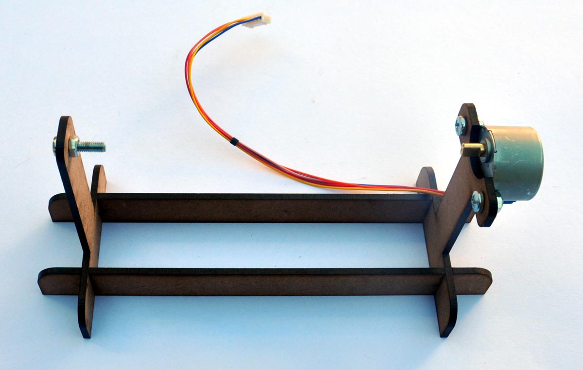
This is straightforward and involves no screws. Connect the two supports to the cross braces by sliding the vertical slits together, and stand them up. The motor shaft and screw should both be pointed inwards. Place the EtchABot body between the supports and slide the motor shaft into the flat-edged slot on the right side of the frame (it may take a little pressure to get it into the slot), and slide the M4 16mm screw through the circular slot on the left side of the frame.
Step 8: Connect electronic components to board
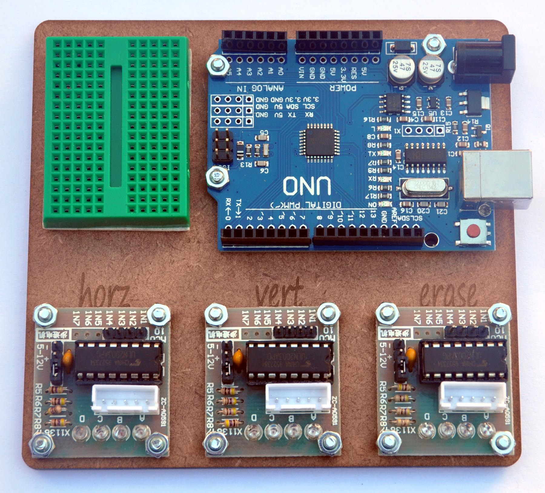
Attach ULN2003 stepper motor drivers and Arduino UNO to the board as shown above with the M3 10mm screws. One screw may not fit well in one of the Arduino holes. If so, just leave it off. Peel the backing off the bottom of the 170 tie-point breadboard and stick it to the base as shown above.
Step 9: Wire the electrical components
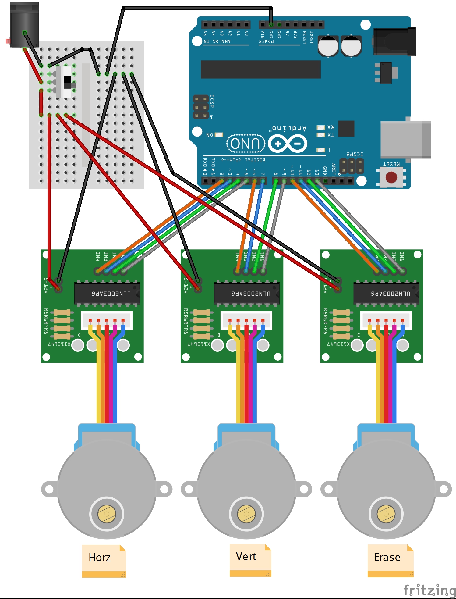
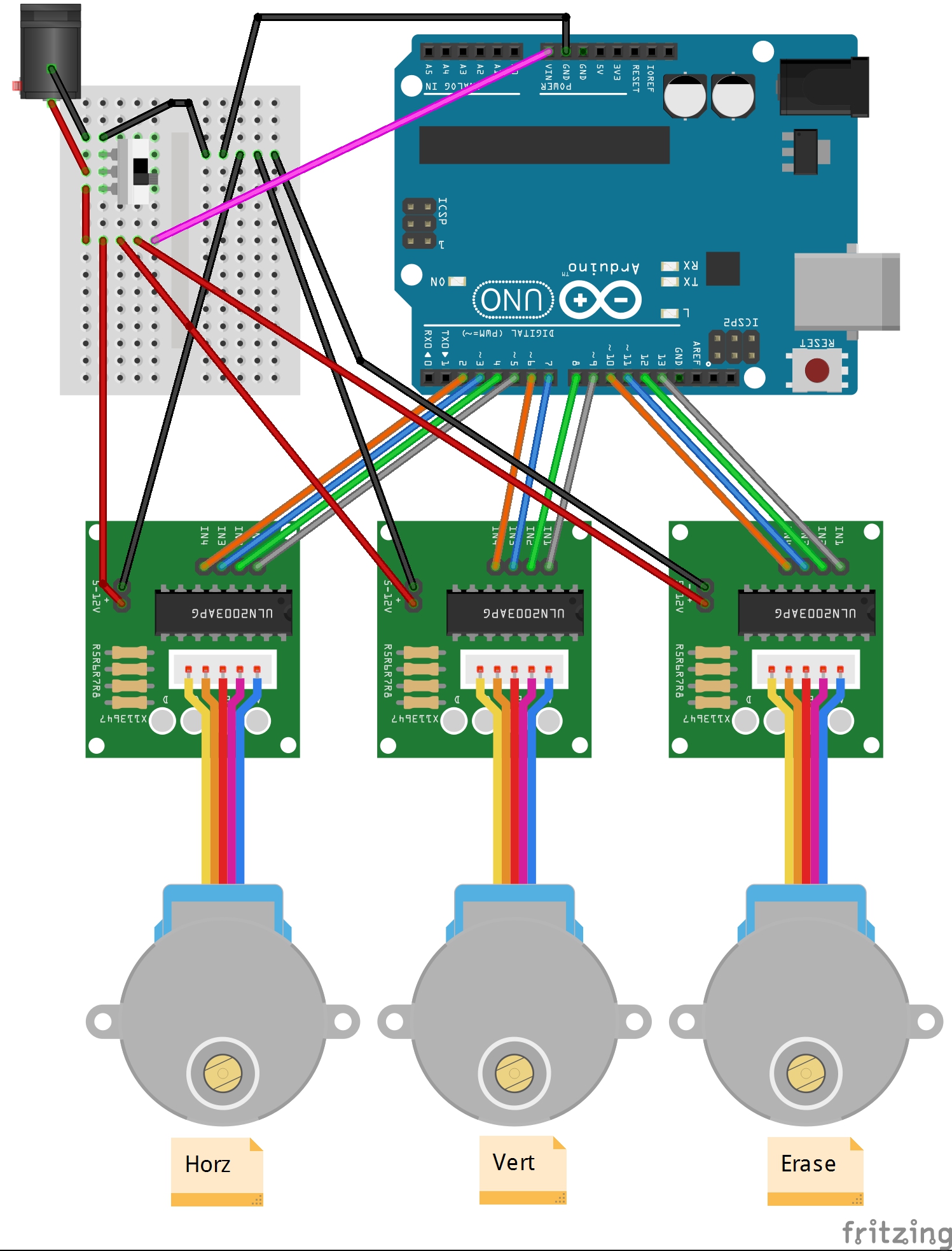
Connect the ULN2003 stepper motor drivers to the Arduino using the 10 cm M-F breadboard cables with pin assignments as follows:
| ULN2003 Motor | ULN2003 Pin # | Arduino Pin# |
| Horz | 4 | 2 |
| Horz | 3 | 3 |
| Horz | 2 | 4 |
| Horz | 1 | 5 |
| Vert | 4 | 6 |
| Vert | 3 | 7 |
| Vert | 2 | 8 |
| Vert | 1 | 9 |
| Erase | 4 | 10 |
| Erase | 3 | 11 |
| Erase | 2 | 12 |
| Erase | 1 | 13 |
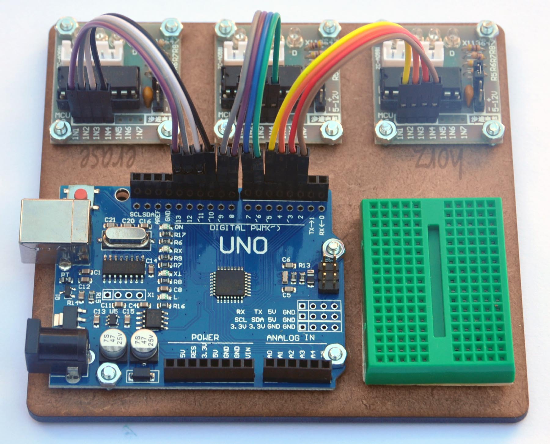
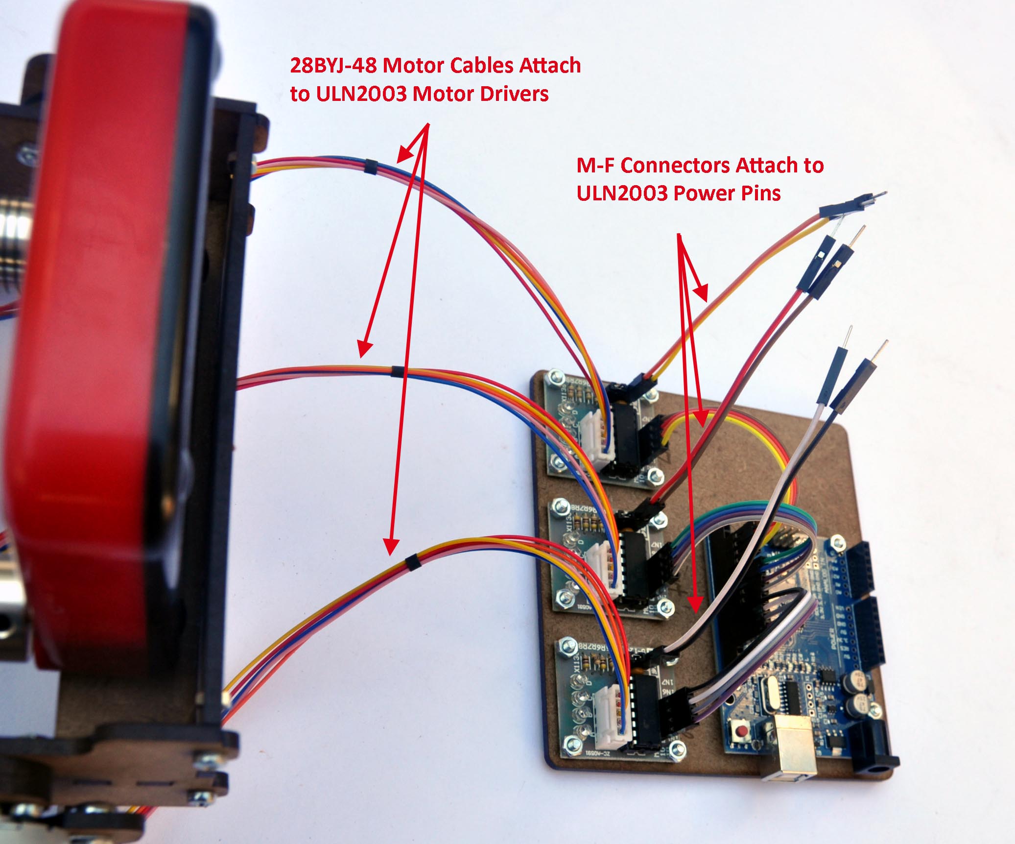
Next plug the 28BYJ-48 motor connector cables into their ULN2003 motor drivers. After that, plug the female side of two female-to-male breadboard cables into each of the ULN2003 motor drivers as shown below:
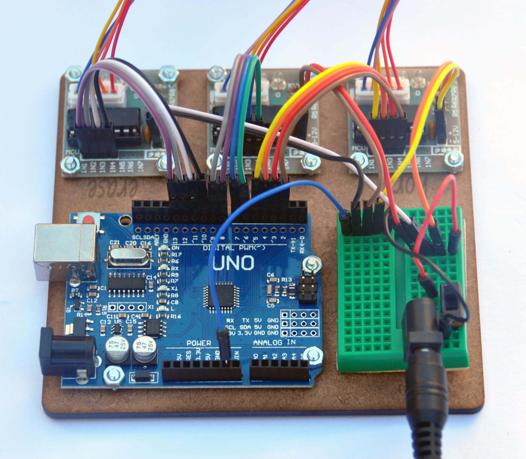
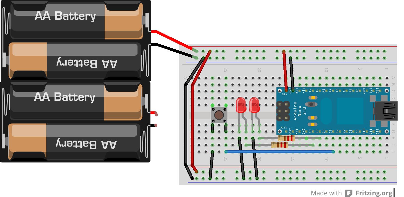
Now wire the power connections on the 170 tie-point breadboard. Use the wiring diagram above for reference. The power from the 6V 1A power adapter runs into the barrel jack connector on the mini breadboard and provides power for the three stepper motors. Do NOT run the power into the Arduino power jack – the motors require more current than should run through the Arduino. When you are programming the Arduino, it will receive power through the USB port. Arduino ground must be tied to power ground as in the diagram. Below is a picture of the wiring on an actual EtchABot.
When running a sketch that doesn’t require a computer, you can power the Arduino from the power jack as well. This requires an additional connection from the positive power to the Arduino Vin pin. (see diagram below – additional connection is in hot pink). Be sure that you don’t connect the computer to the Arduino with the USB cable while the additional power connection is in place. If you do the EtchABot may attempt to power the motors with power from the USB, which pulls too much current through the Arduino.
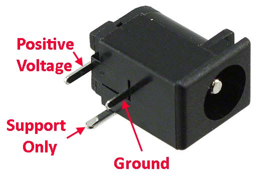
A note about plugging the barrel jack connector into the breadboard. The leg on the side of the jack is for stability and does not run current. The positive lead is at the back of the barrel jack connector and the ground lead is at the middle of the connector. It can be a little tricky to get it to fit into the breadboard, so bend the leads slightly if you have to.
The EtchABot power circuit is wired with a slide switch between the barrel jack connector and the power to the motors. You can leave the switch out of the circuit if you’d like, but then you have to disconnect the power adapter to turn the EtchABot off. The switch makes turning power on and off much easier.
Warning:
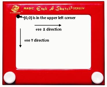
Before running the EtchABot, please be aware that every time you start an Arduino sketch that uses the EtchABot library, it will expect the stylus to be positioned in the upper left corner of the Etch A Sketch. This is the (0,0) position. The EtchABot has no way of knowing where the stylus actually is, and if it does not start in the upper left hand corner, it may attempt to run the stylus off of the screen. This can result in a ruined Etch A Sketch. Please be careful to remember this when running the EtchABot.
Programming EtchABot:
Source code:
Now that the EtchABot is assembled and wired it’s time to make it run! Download all source code from https://github.com/geekmomprojects/EtchABot. I’m new to Git/GitHub, so please let me know if you have any issues downloading. The code is still a work in progress, so you may want to check back for revisions.
The EtchABot library:
The EtchABot library contains an EtchABot class with various functions to control the EtchABot. To run the examples I discuss, you must install the EtchABot library with your other Arduino libraries. See this article on installing Arduino libraries if you need help. Please note that you will also need to have the Arduino Stepper library installed as well, though I believe that it comes standard with most Arduino IDE installations.
The default pin assignments for the stepper motors in the EtchABot library correspond to the motors I used. If you are using your own stepper motors, you may find that your motors run backwards from mine. If this is the case, you will have to change the stepper motor pin assignments in the EtchABot class from the defaults, or swap two of the adjacent pins (NOT the center two) that connect the ULN2003 driver to the Arduino, in order to run the example code.
When using the EtchABot library, you must specify the size of the Etch A Sketch you are using – either Pocket Size or Travel Size. To do this, look for the place in your code where the EtchABot object is created. E.g.:
[code language=”cpp”]
#include <Stepper.h>
#include "EtchABot.h"
EtchABot etch(POCKET_SIZE)
[/code]
The EtchABot code examples:
Several Arduino sketches come with the EtchABot library. They are:
- EtchABotCalibrateBacklash – Draws a pattern with different values for the backlash parameters to determine the best values for a given Etch A Sketch
- EtchABotDriver – Runs as firmware that takes serial input to give the EtchABot commands to perform functions like drawing lines, erasing the screen, and shutting motors off
- EtchABotAnalogClock – When used with a Real Time Clock connected to the Arduino, turns the EtchABot into an analog clock that erases and redraws the time every minute
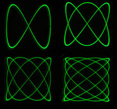
- EtchABotPatterns – Draws a parametric pattern (Spirograph or Lisajous functions, but you can easily add your own) for several minutes, then erases the pattern and starts again
- EtchABotJoystickControl – When used with a small joystick connected to the Arduino, allows the user to control the motion of the stylus and the erasing with the joystick
Checking motor wiring with the EtchABotDriver sketch:
If you are concerned about your motor wiring, it is best to check it before attempting to run any programs on the EtchABot. The simplest way to see if your motors are wired correctly is with the EtchABotDriver Arduino sketch which lets you type simple drawing commands into the Arduino IDE serial window.
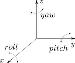
For reference, the upper left corner of the Etch A Sketch screen is defined as (0,0), and the positive directions are down and right (see image). The total Etch A Sketch screen dimensions in units of stepper motor steps are: [6000, 4000] (pocket size) and [6500, 4600] (travel size).
Before starting the calibration sketch, move the Etch A Sketch stylus to the middle of the screen by hand. When the motors are powered off (all lights on the ULN2003 drivers are off) you can turn the shaft couplers by hand to move the EtchASketch stylus. You should not attempt to turn the shaft couplers when the motor drivers are on, as this might damage the motors.
![Line to [1000,1000] runs in SouthWest direction.](http://www.geekmomprojects.com/wp-content/uploads/2015/11/MotorCalibration.jpg)
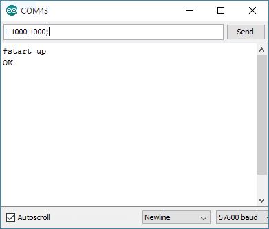
Once the stylus is near the middle of the Etch A Sketch Screen, connect your Arduino to your computer, open up the Arduino IDE and download the EtchABotDriver sketch. After it has downloaded, open up the Serial Window and set the baud rate to 57600. You should see a message saying “#start up/OK“. Be sure the EtchABot is turned on (the motors have power), and type the phrase “L 1000 1000;” into the serial window (exactly as shown without the quotes – the semicolon and spacing is important) and type a carriage return. This command tells the EtchABot to draw a line, in absolute coordinates from the current position, which is assumed to be (0,0) to (1000, 1000). If all is working correctly, you should see a short, diagonal line drawn downwards and to the right. If the line is pointing in any other directions, one or both of your horizontal/vertical stepper motors are wired incorrectly for the EtchABot library.
You can also perform a simple test of the Erase motor by typing “E;” into the Arduino IDE Serial Window. This causes the Erase motor to rotate the EtchASketch forwards then backwards. If the motor rotates backwards, then forwards, it is wired incorrectly for the EtchABot library.
Determining backlash with the EtchABotCalibrateBacklash sketch:
Drawing limitations due to backlash:
Stepper motors are designed for precise movements, and the 28BYJ-48 motors in this project give 2048 steps per revolution when driven in 4-step mode. However, the limitation on drawing accuracy comes from the Etch A Sketch itself. There can be slippage in the stepper motors and backlash in the internal Etch A Sketch drawing mechanism. Running the motors at a slow and steady pace eliminates slippage, but the backlash due to slack in the Etch A Sketch drawing mechanism makes drawing repeatable patterns a challenge.
Taking backlash into account:
If you move the drawing stylus forward 250 steps, then back 250 steps, the stylus will not end up where it started. Instead you need to move a little farther in the backwards direction to account for backlash. It’s even more complicated than that, because if you move horizontally forwards and backwards the backlash will be different than if you go forward, then up, then backwards, and the effect can differ based on the length of the lines draw. Not only does the direction of drawing matter, but the magnitude of the backlash will differ for different Etch A Sketches. It is difficult to compensate for this inconsistency.
The EtchABot class contains a set of horizontal and vertical backlash parameters that can be adjusted dynamically in the code. When the EtchABot drawing function detects that the direction of motion has changed, it attempts to compensate by adding a few extra steps in the new direction to take up the slack from the backlash. This method works reasonably well in certain circumstances, such as drawing horizontal and vertical lines, and not particularly well when drawing curved lines. The Spirograph sketch sets the backlash parameters to zero for this reason.
In the images below the same image has been drawn twice. The top image has been drawn with a backlash correction of [0,0] and the bottom image has been drawn with a backlash correction of [120,120] for comparison. Click on an image to enlarge.
The upshot of all this is that sometimes it’s good to correct for backlash, and sometimes it’s not. You may have to determine what’s best for each particular drawing.
Calibrating backlash correction:
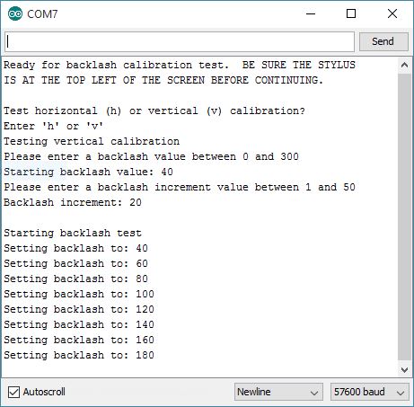
Before running the Arduino sketches that correct for backlash, it’s a good idea to calibrate the backlash correction values. Good backlash calibration will be useful when drawing raster images, for example. To run the backlash calibration, download the EtchABotCalibration sketch to the Arduino, and run your Arduino IDE in serial monitor mode. You should see the screen below. You will need to enter (1) whether you want to test horizontal or vertical backlash, (2) a starting value, and (3) the a value to increment the backlash by for each step. The sketch will test 8 different values for the backlash parameter, increasing the value by the specified increment with each step.
The EtchABot should draw a pattern that looks something like this (for vertical calibration):
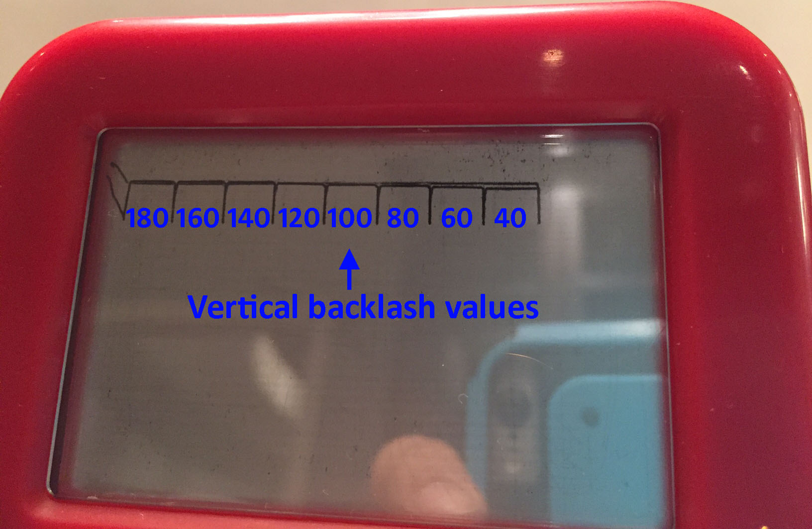
Run the program twice – once for horizontal, and once for vertical calibration. The results for vertical calibration are shown in the image above. The best backlash calibration value is the one where the lines completely overlap. Often this is with a value somewhere in the range of 100 to 140, but it does vary.
If you want to change the values of backlash correction used in an Arduino sketch, you can add a couple of lines of code. Just look for the point in the code where the EtchABot object is created:
[code language=”cpp”]
EtchABot etch(POCKET_SIZE);
[/code]
and add the following lines of code to change the backlash settings (substituting your own values for the “100”).
[code language=”cpp”]
etch.SetHBacklash(100);
etch.SetVBacklash(100);
[/code]
Analog clock mode with EtchABotAnalogClock sketch:
To turn your EtchABot into an analog clock, you will need a Real Time Clock (RTC) breakout board. The EtchABot kit comes with a DS3231 RTC, and a LI2032 Coin Cell Battery to keep the correct time even when the Arduino is off.
Before doing anything else, you must set the correct time on the RTC. RTCs don’t adjust for Daylight Savings Time, since it differs by location, so if your RTC has been set more than 6 months ago, you will probably need to reset the time. This Instructable has easy to follow instructions to set the time.
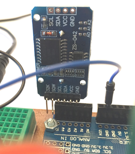
Once the time is set, connect the RTC to the Arduino. I found the easiest way to do this is to use pins A2 and A3 for ground and 5V power respectively (by setting them to LOW and HIGH in the Arduino sketch), and SCA and SDL connect to A4 and A5 respectively. This allows you to plug the RTC board directly into the Arduino UNO. The extra pins on the RTC simply hang over the edge as seen in the picture above. If your RTC pins are ordered differently, you can also simply bend the extraneous pins out of the way. If your RTC Vcc and GND pins are backwards from mine, you must change the pin assignments the Arduino EtchABotAnalogClock sketch.
Setting up and running the code is easy. Simply download the EtchABotAnalogClock sketch to the EtchABot, making sure that you’ve correctly set the Etch A Sketch size to POCKET_SIZE or TRAVEL_SIZE in the code, and that your pin assignments correspond to your RTC board. Be sure the stylus is positioned in the upper left corner of the Etch A Sketch before turning on power to the motors.
The analog clock sketch requires no computer connection to run, so you can disconnect the USB cable from the UNO, and run a jumper from the breadboard positive power (+6V) to Arduino Vin, as shown by the pink connection in this image.
Once the wiring is done, turn on the power to the motors and the Arduino, and you should see something like this:
Spirograph mode with EtchABotPatterns sketch:
To draw parametric patterns with the EtchABot, download the EtchABotPatterns sketch to the Arduino. By default, the sketch displays a changing Spirograph pattern for several minutes, then erases it and starts again. If you read the sketch, you will see several parameters that you can customize:
[code language=”cpp”]
#include <Stepper.h> // Must include this if we will use "EtchABot.h"
#include "EtchABot.h"
#define DEGREES_T0_RADIANS 0.0174533
#define RESET_MINUTES 4 // # of minutes after which we reset the pattern
// Pick one of the options below to define the type of curve
#define SPIROGRAPH
//#define LISAJOUS
[/code]
Simply change the RESET_MINUTES parameter to change how long the pattern will draw before being erased. Uncommenting either the SPIROGRAPH or LISAJOUS define statement will determine the kind of pattern drawn. The Lissajous pattern takes longer to draw than the Spirograph, so you might want to give it a few extra minutes to draw if you choose it.
Like the analog clock mode, the computer does not need to be connected for the sketch to run, so you can disconnect the computer from the Arduino USB, and wire up Arduino power from the Breadboard to Vin as shown here.
Be sure the stylus is in the upper left corner of the Etch A Sketch screen, turn on the power, and voila! A self-erasing Spirograph!
Joystick control mode with EtchABotJoystickControl:
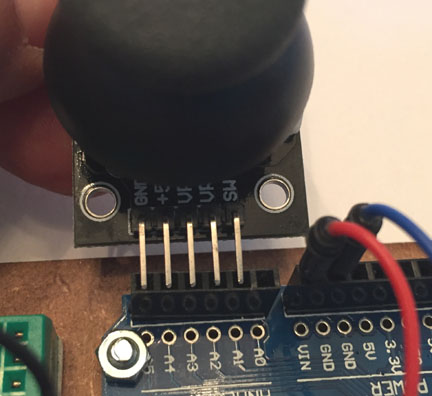
You can use a thumb joystick to control the drawing and erasing functions of the EtchABot. The EtchABot kit comes with one, or you can provide your own. Wiring it up is easy. The joystick usually has 5 pins: GND, VCC, Vx, Vy, SW (SW = switch). You can plug those directly into the row of analog pins as shown, so that the wiring is: GND → A5, Vcc → A4, Vx → A3, Vy → A2, SW →A1.
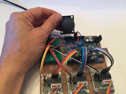
Next download the EtchABotJoystickControl sketch to the Arduino. You can then unplug the computer USB cable, and wire up power from the breadboard to Arduino Vin to run without a computer connection. Be sure the stylus is in the upper left corner before turning on the EtchABot. Turn it on and move the joystick to direct the drawing on the Etch A Sketch. Press down on the joystick to erase the EtchABot.
Drawing Images with EtchABot:
This post has gotten very long, so I’m going to write up how to get the EtchABot to draw images – vector, raster and freehand in a second post. Happy Etch A Sketching!
Wait… No gcode?
Hi. did you do the grafics in fritzing? If yes, could you provide the ULN2003A-part as fzpz file?
Hi Christoph,
Yes, I used Fritzing. I found the ULN2003 fzpz file online, and I can’t remember exactly where, but I think it was here: https://github.com/lambert/fritzing-parts – there are a bunch of Fritzing parts in a Zip file and ULN2003A is one of them. Hope that helps.
Debra