
MeArm is an open-source robotic arm kit by Benjamin Gray and Jack Howard. They published design files for their robot on Thingiverse and a set of instructions on Instructables. You can 3D print or lasercut the parts, or you can order them as a kit which includes all servos and screws from Adafruit. If you create the parts yourself, you’ll need to purchase four 9g servos and assorted lenghts of M3 screws to complete the assembly.
I imported the MeArm PDF file from Thingiverse into Inkscape, and re-arranged a couple of the components, so that I could fit two entire setups onto a Ponoko P2 template. I uploaded the design to Ponoko in EPS format to be cut from 3mm blue acrylic, and received it a few days later.
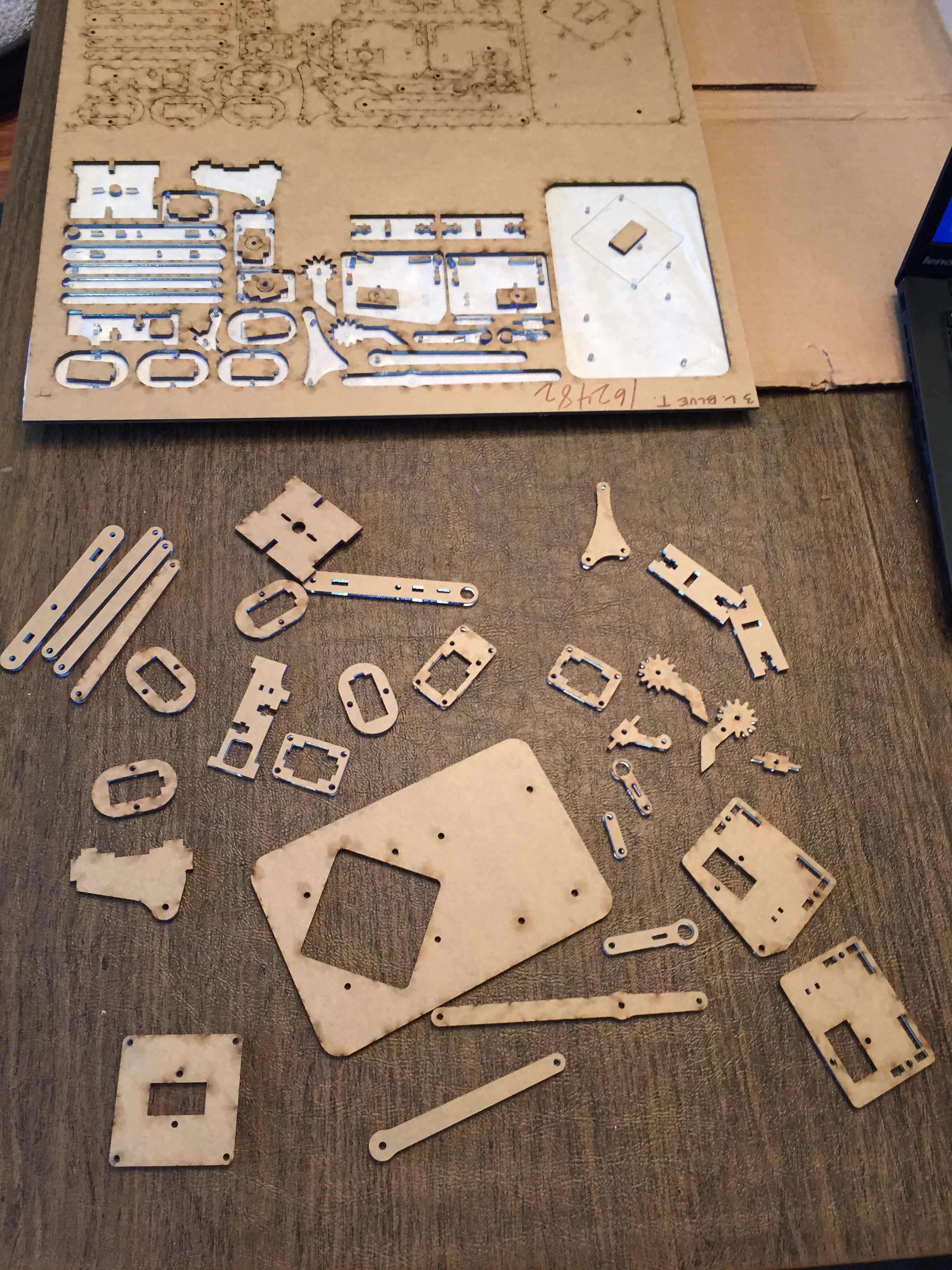
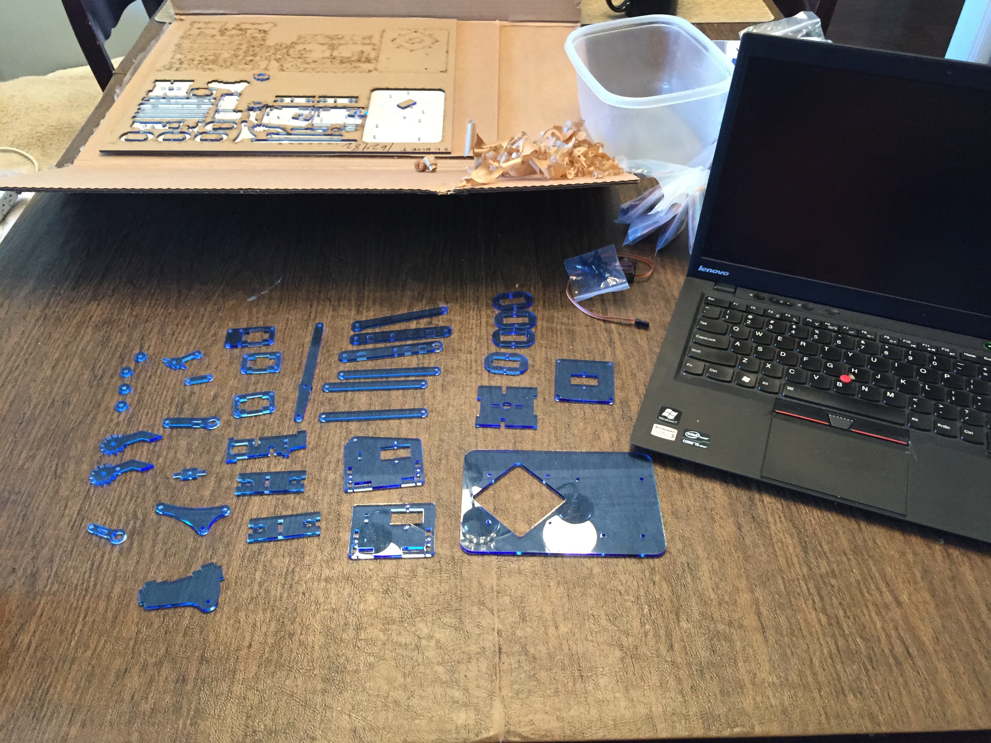
The MeArm construction process is very well documented on Instructables, and is straightforward to follow. Building the arm took a little over two hours. I already had all the different lengths of M3 screws that were recommended, and I ordered metal gear servos, as they were recommended as being sturdier. The only significant comments I have on the build are as follows:
- Some parts that are joined by screws are supposed to fit together snugly, and some are to rotate freely. Where parts need to rotate, I found it worked best to tap the screw holes with an M3 tap before inserting the screw.
- The servos are attached with clever “collars” that hold them in place. My collars were so snug that to get them to slide around my servos, I had to peel the labels off of the servos, and even file down the outer surface of the servo to get the collar to slide on.
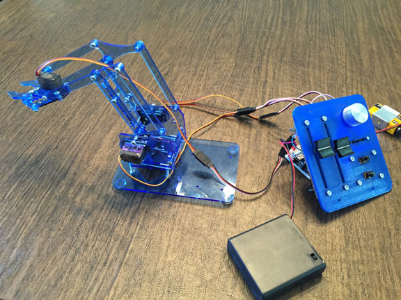
Once the arm was constructed, I used some linear and rotational 10K potentiometers I had lying around to create a controller. I 3d printed a surface to hold the pots, then connected them to an Arduino Nano as inputs. Currently each pot controls one servo directly – three for movement and one for the gripper.
Here’s a demo of using the controller to move the MeArm:
I’m not totally sure what I’ll do with the MeArm, but perhaps when I finish the second one, I’ll program them for robot battle!
Great project! And it moves so fluid.. The controller was all built by you? Could you share the EPS used on Ponoko to lasercut the arm? (PS: great blog! following!)
Hi Marco,
Thank you. It is a clever design. The original files in .dxf and .pdf form can be found at thingiverse: http://www.thingiverse.com/thing:360108/#files. When I uploaded it to Ponoko, I put two complete sets of MeArm parts on a single template. I made the Ponoko template I used public at http://www.ponoko.com/showroom/GeekMomProjects, and the .eps file is here: http://www.geekmomprojects.com/download/mearm-eps-template/
I did build the controller – it’s very basic, just three linear potentiometers and one standard potentiometer to control the four servos. Have fun with your project!
Debra
Thank you so much for the quick reply, Debra! I think I’m going to use your “mirror” design.. Not that great with EPS to adapt it for a single arm.. 😐
It is, indeed, a clever design for it’s simplicity.. I wonder how easy would be to use cheaper/weaker servos. Do you think it would clog the fluid response of the controller?
Thanks
If you use Inkscape (free software), you should just be able to cut out the parts from the .eps file for a single MeArm. I think that standard servos will work fine – many people have used them, and they seem to work just as well. I don’t think it will affect the fluidity, but it may affect the maximum torque you can get before the servo arm slips.
Hi!! Congrats! Really nice project. Did you experienced a “reset” on the servos during the start up? I assembled V0.3 and everytime I turn the Arduino “on” the servos go to zero very fast, this caused broken grips and some joints also. Any idea about what could be causing this?
Hi Sergio, thanks – I didn’t experience anything like what you’re describing, however it sounds like it could be a result of possibly initializing the servo angles to zero in the Arduino code. If not that, I’m not sure what it could be.