The Inspiration:

I’ve been very slow to create posts these last few months. I like to think it’s not due to laziness, but just that I’ve been so busy playing with other projects. I’m pushing myself to write up the more interesting ones. These days I’ve been obsessed with machines that draw. The biggest of these projects has been my wall plotter, nicknamed YAWP (Yet Another Wall Plotter).
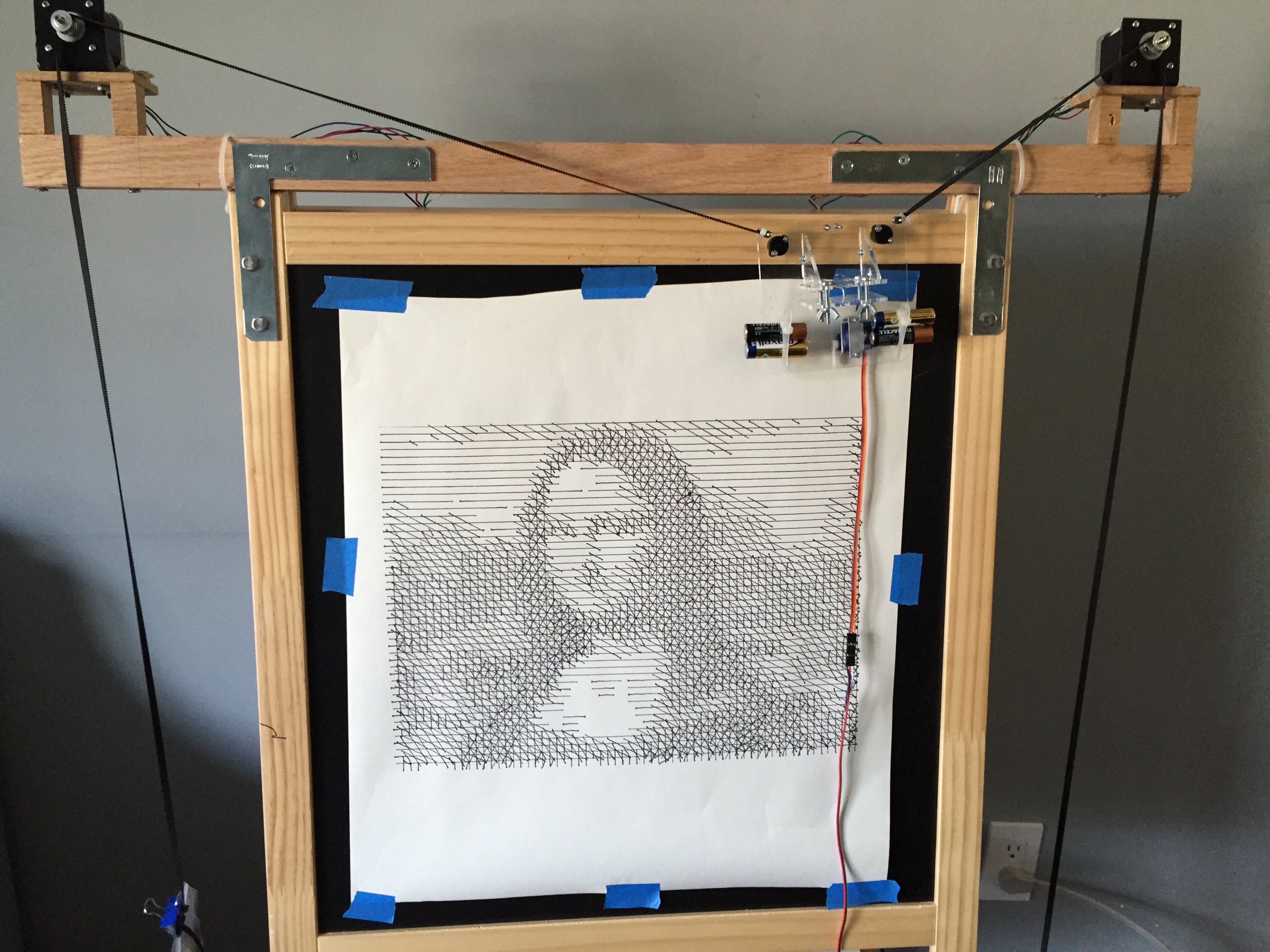
A wall plotter (also known as V-plotter or polargraph) works by moving a pen around a vertical (or slightly angled) drawing surface by means of two motors attached to string or a timing belt. Although wall plotters are really just very slow, low resolution printers, the potentially unlimited scalability and numerous variations in the output make them compelling to watch. Because of their simple design and because it’s fun to watch a machine drawing with a pen, they are far more engaging than a typical desktop printer.
There are many different wall plotter projects online, with varying degrees of documentation. Two aggregate lists of other online wall plotter projects are below:
YAWP was based mainly off of Der Kritzler machine, whose creators have published abundant documentation and schematics. They document a pen carriage, a printed circuit board for electronics, and their code – both firmware for an Arduino and image processing software (written in Processing) to run on a computer. I used their circuit design and Arduino firmware almost verbatim, but designed my own pen carriage and software.
The Computer Setup:
I used Der Kritzler’s Arduino firmware almost exactly as written, making only small changes to reflect the physical size and coordinates of the canvas and the locations of the stepper motors. The Arduino code tracks the location of the pen carriage and receives commands via the USB port in the format, “M x y” or “L x y”, where M and L specify to Move the pen carriage (pen up) or draw a Line with the pen carriage (pen down) to the point with coordinates (x,y). x and y are specified in units of 0.1 mm, though YAWP’s actual drawing resolution is not that precise.
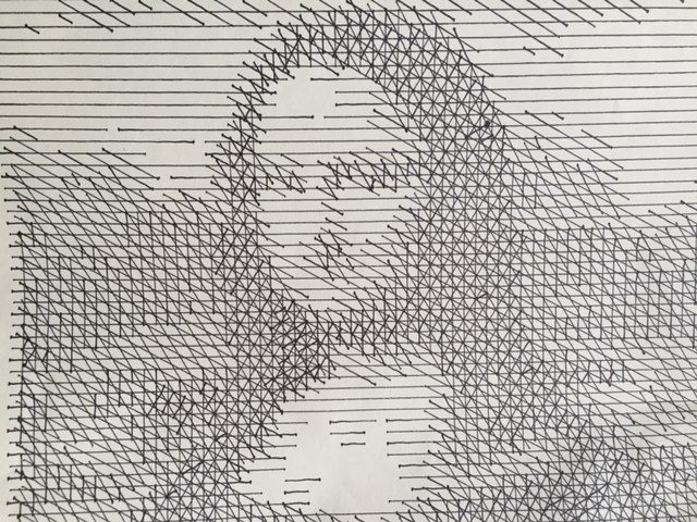
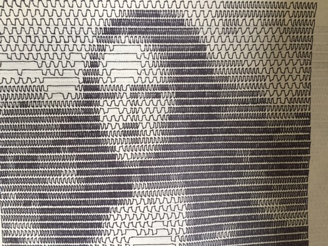
I wrote my own Python software which can run either on my Windows laptop and on a Raspberry Pi. This code allows the user to select an image, then it re-scales the image resolution to no more than 64 pixels on a side. Since the drawing area is 42 by 35 cm, each canvas “pixel” is approximately 1/2 cm in size. The Python software converts the low-resolution image to a series of commands to move the pen carriage around the board. The program gives a choice two styles of raster drawing, “jitter” and “crosshatch”. “Crosshatch” simply draws intersecting straight lines at different angles across the board while “jitter” draws horizontal lines across the board with vertical perturbations that become denser for darker pixels. I tried to get vector drawing to work, and the program can take in simple gcode files and draw them, but only with a very limited set of gcode commands.
Some of the built-in Python image processing libraries were very helpful when writing the software. In particular, PIL for image processing, and PyGame for image display.
The Mechanical Parts:
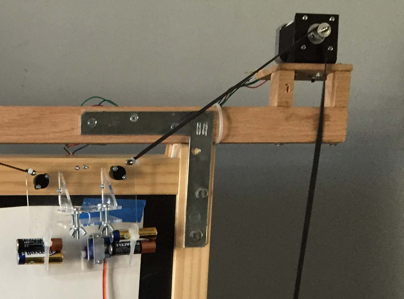
Frame: While the Der Kritzler plotter was designed to draw on windows (the glass kind, not Microsoft), I used an IKEA easel for the frame, because they are cheap, free-standing and portable. In addition the IKEA easel has a bar to hold rolls of paper and a convenient tray which I used to hold the electronics. Because the optimal drawing area is significantly smaller than then spacing between the motors (see http://2e5.com/plotter/V/design/ for explanation), I attempted to maximize the drawing surface by mounting the motors on wooden extensions to the easel frame, held in place by angle brackets.
Pen Carriage: I wanted a pen carriage that could hold different sized pens and was transparent to allow the drawing to show through. I designed one in Inkscape to be lasercut from 3 mm clear acrylic, then uploaded the SVG file to Ponoko for cutting. The pieces are joined with M3 screws (and smaller screws to hold the servo). The pen (a fine-tipped Sharpie) is sandwiched between two flat pieces of acrylic, held together with long M4 screws and wingnuts. The flat pieces have etched lines showing the proper pen placement.
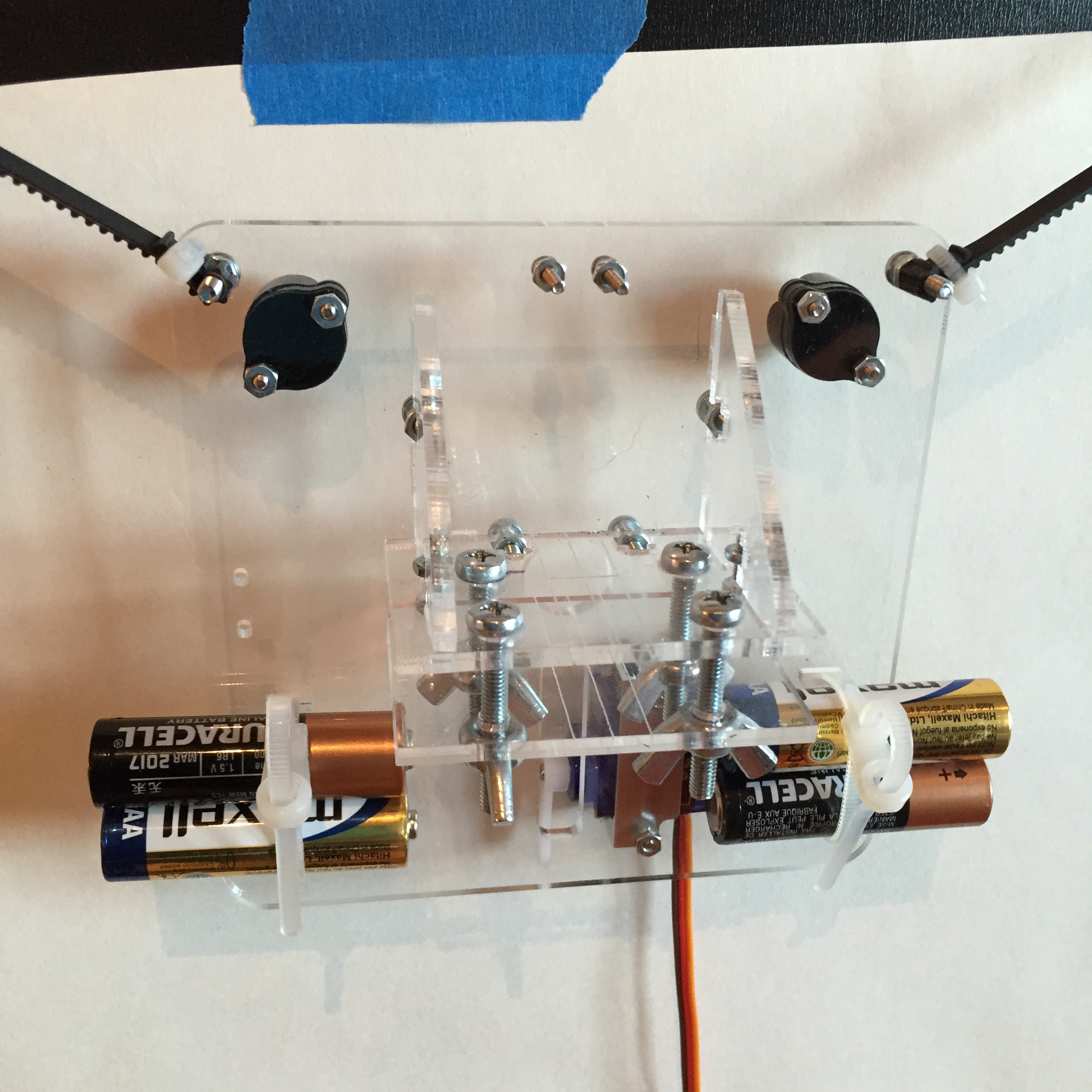
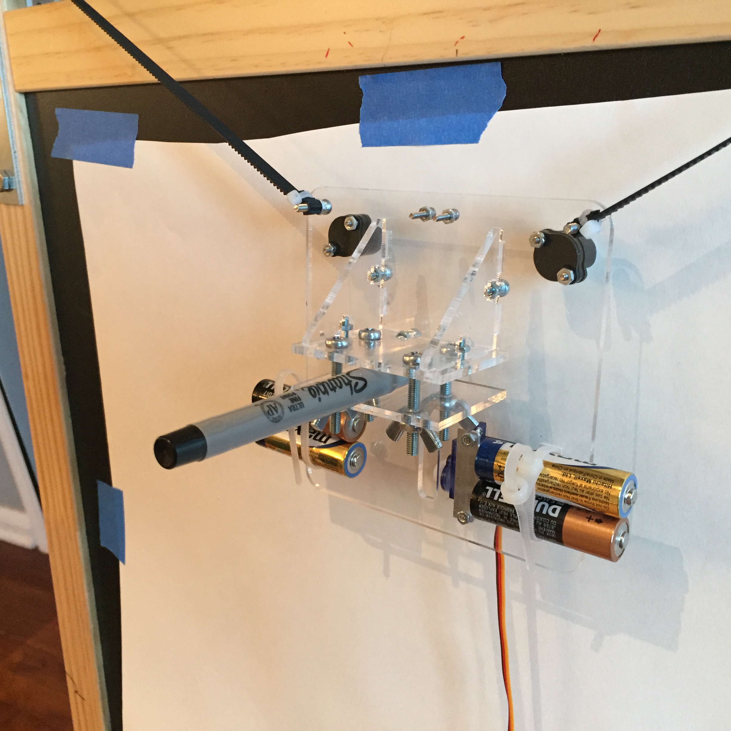
A 9g servo motor is attached to the underside of the carriage by a servo motor bracket. The servo arm can lift the pen off the paper for motion without drawing. Dead batteries, used for weight only, are held in place with zip ties. At the top corners of the pen carriage are Pololu ball casters to add stability. The carriage is always resting 3 points on the drawing surface, the two ball casters and either the pen (when in drawing mode), or the servo horn (when in moving mode). The pen carriage is supported (and transported) by two lengths of GT2 timing belt, which wrap around pulleys attached to the stepper motor shafts.
The Electronics:
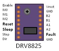
The electronics were copied very closely from Der Kritzler. Pololu DRV8825 motor drivers power and control Pololu Stepper Motors. The motors are rated for 4 Volts and 1.2 Amps, but can run with higher voltages as long as you set a current limiting resistor on the motor driver. The DRV8825’s resistor is controlled by a tiny potentiometer which is hard to turn precisely. You can measure a reference voltage on the potentiometer, which is related to the current limit by 2*Vref = Ilimit. This page is very helpful in understanding the motor driver settings. With care and many attempts, I managed to set Vref = 0.55 volts, which will keep the current under the 1.2 Amp limit. The drivers are fed by a 12 V regulated power supply.
The drivers can run the stepper motors in “microstepping” mode – i.e. they can take fractional steps – reducing the minimum step size. Setting the MS0, MS1 and MS2 pins high/low yields the following settings:
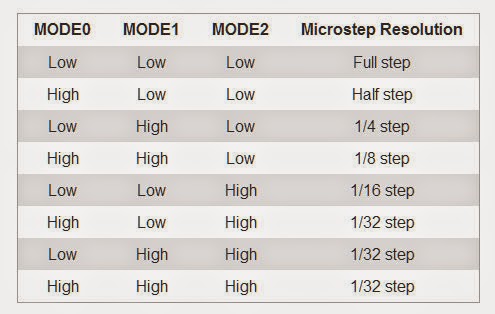
Like Der Kritzler, YAWP ran the Stepper motors in quarter-stepping mode, which increased the motors’ base property of 200 steps/revolution to a possible 800 steps/revolution.
One Arduino Nano runs two DRV8825 drivers for stepper motors A and B, and the Arduino is wired as follows:
- Pin 11 -> indicator LED
- Pin 12 -> indicator LED
- Pin 7-> Step A
- Pin 8 -> Dir A
- Pin 2 -> Step B
- Pin 3 -> Dir B
- Pin A1 -> MS2 (A and B)
- Pin A2 -> MS1 (A and B)
- Pin A3 -> MS0 (A and B)
- Pin A4 -> Enable (A and B)
- Pin 5 -> Servo Motor (for lifting pen carriage off the canvas)
Each stepper motor is mounted with a GT2 Pulley to pull the timing belts, which, in turn, rotates to move the pen carriage around the drawing area.
The Theory:
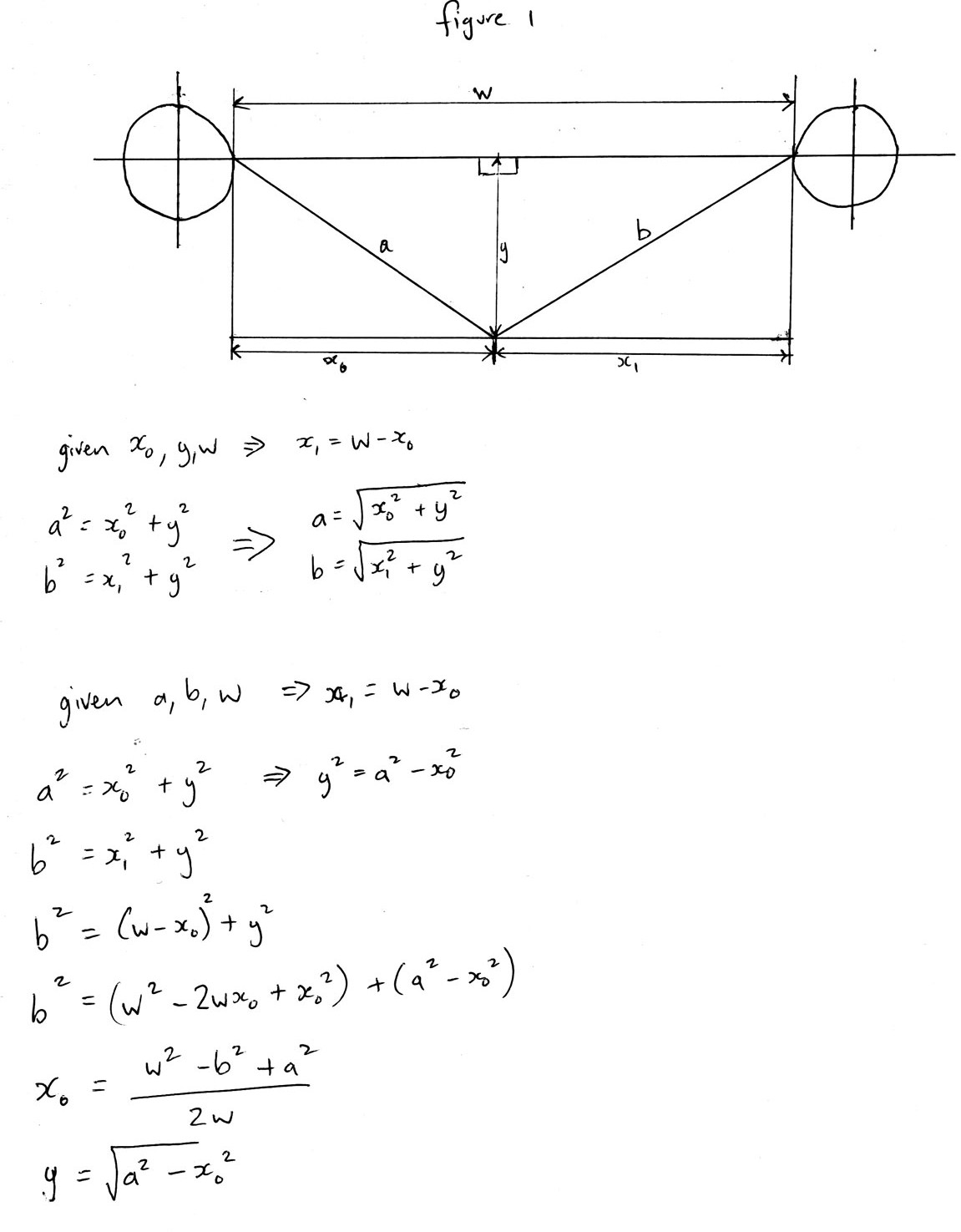
The trick of wall plotter geometry is to convert the rotational motion of the stepper motors to x-y coodinates in the drawing area. Below is an example of the computation to convert string lengths (a and b) to coordinates (x, y)
Additionally the change in string lengths is related to the number of steps of the stepper motor by the formula:
Change in length = (# steps) (radians per step) (pulley radius)
So if we know the current position and where we want to send the pen, we can compute how many steps each motor needs to take. That gives us the beginning and end points of a line, but we also need to calculate the intermediate points. Otherwise, if we just moved one motor first, then the other, we’d end up with an L-shaped path between points.
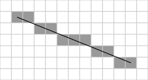
Der Kritzler’s firmware uses Bresenham’s line algorithm to compute the best incremental path between two plotter points. This algorithm computes which steps are best taken on a discrete grid to simulate a straight line. While this algorithm works well on a flat surface, I found that any line longer than a few centimeters on YAWP’s almost vertical drawing surface was noticeably bowed. The solution to this was to set the the software to break up any long lines into maximum lengths of 1 cm, before sending the coordinates over to the Arduino.
The drawing also gets distorted when the tension in one of the pulleys is too high, causing the pen carriage to pivot, or too low, leaving slack in the timing belt. Having the pen located where the timing belts would meet if they were extended is helpful, because the carriage tends to pivot about that point. Weights are necessary to supply sufficient tension in the timing belt both to prevent slack and to maintain a good grip on the pulleys – hence the dead batteries attached to the pen carriage, and additional weights on the other side of the timing belts.
Operation:
The plotter needs to know its initial position before it can start. I toyed with the idea of making it self calibrating, but found it much easier in the end, to just line it up with a known point (the midpoint at the top of the frame) before starting each time. I got the software working on a Rasberry Pi, and purchased a small monitor and tiny keyboard/touchpad to make the whole thing portable. Once it gets going, most reasonable size images take about an hour to draw.
The Results:
This video shows YAWP creating a drawing in shaded mode:
and below is a time-lapse video of YAWP drawing in crosshatch mode:
The Future:
I’m currently working on a scaled-up version of YAWP which will use a larger easel constructed from PVC pipe and a dry erase board, rather than a wooden easel holding paper. The goal is to have it ready for display by mid-April so it can be an exhibit at a science fair at my children’s school.
Hello,
I am really interested in your draw plot project with the arduino and the raspberry pi. I have a questions. Where can I find the sketch, which you are used for the raspberry pi and the arduino?
I had downloaded the firmware of Kritzler but I dont know how to program the image software for the pi.
I am pleasent if you give me an answer.
See you soon…
Adrian Höppener
Hi Adrian,
I haven’t published the Python code I wrote for the Pi, mostly because I didn’t know Python when I started it, and it’s not very well written. It was also a little tricky to get some of the Python modules I used to compile on the Pi – though with a lot of help from Google, I figured it out. If you are still interested, I can email you the code. I will be able to get around to it in the next couple of days.
Debra
hello
great project
I’m still interessed in the py code.
specialy the part to comunicate via serial with the arduino..
Can you tell me if you have pushed somewhere or where I can find it…
thanks in advance if you give me an answer.
Giacomo
Hi Giacomo,
I apologize for the delay in releasing the code. I have put the python code I used on Dropbox, under this link: https://dl.dropboxusercontent.com/u/24233565/WallPlotter.py. It works, but I haven’t cleaned up the code at all, so I hope that it makes sense to you. It runs under Python 3 on the Rapsberry Pi, and requires several Python modules to be installed, some of which I found challenging to install on the Pi. The modules are listed at the top of the program. The “serial” module is used to communicate with the Arduino. I connected the Arduino directly to the Pi via their serial ports. That part is fairly straightforward, and there is a lot of information online about interfacing an Arduino and Raspberry Pi.
Good luck with your project, and I hope this is helpful.
Debra
Wow Debra…
You already answer to me…
I realy appreciate it.
I haven’t try it but I will do it soon… and I will give back my feedback.
Thanks a lot for now…
good luck to you.
Giacomo
The dropbox url gives a 404 error. Is the code now listed somewhere else?
Ooops, yes it was broken. Try this link:
https://www.dropbox.com/sh/pecrqhw88k6c82n/AABWPMj0EkJ6tRQTrJlOgOw5a?dl=0
Hi Debra,
Really interesting project. I have two questions:
1. Where did you buy components like the servo and stepper motors?
2. How long did this project take you to work through?
Many Thanks!
Hi Oli,
Thanks! I don’t remember where I bought the components for this specific project, though I usually buy NEMA 17 steppers, servos and motor drivers on EBay, as it’s cheaper there. Be careful though, sometimes the motors advertised on EBay have been used in other projects. You can also buy stepper motors, servos and drivers from electronics sites like adafruit.com and sparkfun.com.
It took a while to figure out this project – several months on a very part-time basis, but most of the time went into the design of the pen carriage and the software for the Raspberry Pi (the Arduino firmware was lifted directly from another project, so that was easy). The pen carriage took a while because I was mail-ordering the laser-cut parts, and I had to go through a few iterations before I got it right. Actually building out the mechanical and electronic components wasn’t too bad – probably about a week or two.
Hope that helps.
Debra
Great Proyect!!!! Just one question, why did you use an arduino nano, for driving the stepper drivers, and not drive the drivers directly from GPIO from the raspberry pi?
Hi Lukas,
Thank you! The only reason I used an Arduino to drive the motors was that someone else had already written firmware for Arduino that I was able to use directly. I took the motor control code directly from the “Der Kritzler” wall plotter project. If I had put everything on the Pi, I would have had to write or adapt the code myself. Basically it was laziness on my part. Hope that answers your question.
Debra
hello good job buddy..
i was planning to make this plotter, can i know whether i can draw the path which is drawn by me or if i draw something on pc can i plot that on the sheet..
Hi! Thanks for posting this information, was looking for a polargraph/drawbot built on simpler hardware than 2560-based boards, unfortunately it seems it doesn’t compile with current libraries as of this time of writing. I get loads of compile error with both arduino nano or arduino pro mini boards and it seems to originate from the TimerThree lib.
i.e.:
error: ‘TCCR3B’ was not declared in this scope
TCCR3B = _BV(WGM33); // set mode as phase and frequency correct pwm, stop the timer
error: ‘WGM33’ was not declared in this scope
TCCR3B = _BV(WGM33); // set mode as phase and frequency correct pwm, stop the timer
…
Any clues? And thanks again for your post!.