
I’ve been using the GY-521 IMU breakout board containing Invensense’s MPU-6050 IMU to compute orientation in my self-balancing scooter (the “Halfway”). I’d like to improve the scooter’s performance on hills and uneven surfaces. I thought I’d revisit the fusion algorithm which combines gyroscope and accelerometer data to compute the scooter’s tilt angle. The initial code for the Halfway used a complementary filter algorithm, explained in an earlier blog post. Accelerometer data is noisy on short time scales, and gyroscope data drifts on longer timescales, so the complementary filter combines both for greater accuracy. However, the MPU-6050 contains a digital motion processor (DMP) which can perform the data fusion on the IMU chip iteslf. Though the exact details of how the DMP does is calculations are not published, the DMP is still useful because presumably Invensense has a pretty good fusion algorithm and because the DMP calculations occur on the MPU-6050 chip, freeing up processor power. I wrote about using the i2cdevlib library to obtain orientation data from the MPU-6050 DMP in this post. I’d made earlier attempts to compare the DMP and complementary filter data, but I kept running into problems retrieving data from the FIFO buffer on the MPU-6050. The FIFO buffer would overflow while the Arduino program was performing the complementary filter calculations. I found the fix for that in the i2cdevlib forums here. The solution is to reduce the rate at which the DMP writes to the FIFO buffer. In the i2cdevlib library, the FIFO rate is controlled in line 305 of the file “MPU6050_6axis_motionapps.h” (the exact line number depends on which version of the file you’re using)
[cpp firstline=”303″ gutter=”true” language=”++”]
0x07, 0x47, 0x04, 0xF1, 0x28, 0x30, 0x38, // CFG_9 inv_send_gyro -> inv_construct3_fifo
0x07, 0x6C, 0x04, 0xF1, 0x28, 0x30, 0x38, // CFG_12 inv_send_accel -> inv_construct3_fifo
0x02, 0x16, 0x02, 0x00, 0x01 // D_0_22 inv_set_fifo_rate
// This very last 0x01 WAS a 0x09, which drops the FIFO rate down to 20 Hz. 0x07 is 25 Hz,
// 0x01 is 100Hz. Going faster than 100Hz (0x00=200Hz) tends to result in very noisy data.
// DMP output frequency is calculated easily using this equation: (200Hz / (1 + value))
// It is important to make sure the host processor can keep up with reading and processing
// the FIFO output at the desired rate. Handling FIFO overflow cleanly is also a good idea.
[/cpp]
Initially, the FIFO write rate was 100 Hz, which overflowed the buffer easily. Reducing the rate to 20 Hz allowed enough time to complete the complementary filter calculations before retrieving the DMP data. I took Jeff Rowberg’s Arudino sketch which extracts the DMP data and modified it to perform the complementary filter calculations as well. The Arduino sketch then sent the data over the serial port to a Processing sketch to display it graphically. Please note that Rowberg’s code can calculate orientation angles in terms of either yaw, pitch, roll angles or Euler angles. I’m not clear on the difference between these two sets of angles (If someone can explain it to me, please let me know!) In i2cdevlib the computation of the yaw, pitch, roll angles incorporates the gravity vector and seems to best match the data from the complementary filter, so that is what I chose for the comparison. Below is a screenshot from the Processing sketch:
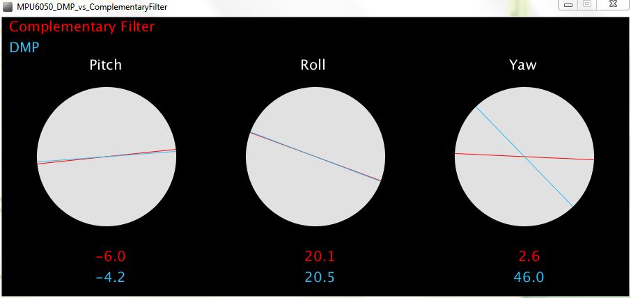
Below is a video comparison between the orientation angles from the MPU-6050 as calculated by the DMP and the complementary filter algorithm. I don’t have any quantitative data showing which algorithm is better. Qualitatively, however, I can say that for pitch (rotation about the X-axis) and roll (rotation about the Y-axis), the calculations are fairly close, but the complementary filter seems to consistently lag the DMP. The DMP algorithm is able to calculate yaw, which the complementary filter cannot. I suspect that when the algorithms differ, the DMP is more accurate, however it is possible that a better implementation of the complementary filter might be able to reduce some of the lag.
Here is the Arduino code that generates the data. It requires i2cdevlib to work, and as discussed above, the DMP FIFO rate should be set to about 20 Hz:
Here is the Processing sketch to display the data: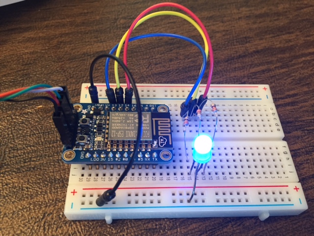
You have done it again! Impressive work!
I tried to download documentation regarding the MPU6050 from Invensense’s homepage.
And specifically concerning the DMP.
But I got the following feedback in the error message: “Your status is too low”.
And at the same the Invensense Company invited me to an event in California 🙂
Anyone who have succeded to download more than the Manual/Register-stuff??
Forgot to mentioned this in my previous reply:
I have sent an request to Invensene what I can do to “Raise my status”.
No response at all so far.
They are probably occupied with their event in California, should have gone their.
But it’s too expensive from Sweden!
Regarding information/documentation from Invensense:
I found more Invensense documents by using this link:
http://www.i2cdevlib.com/forums/topic/153-official-dmp-documentation-is-released-by-invensense/
Please go to post #15
I have now tested Your sketches and it worked randomly on my PC. Sometimes it run for 2 minutes sometimes it run less than 10 seconds. (I am running a MPU6050 BreakOUTBoard from Sparkfun)
I’m not sure that I got the “DMP FIFO rate” Set Up right.
In the documents from Invensense I fond the following, I Quote:
“Known Bug:
DMP when enabled will sample sensor data at 200Hz and output to FIFO at the rate speciefied ind the dmp_set_fifo_rata API. The DMP will then sent an interrupt once a sample has been put into the FIFO. Therefore if the dmp_set_fifo_rate is at 25Hz there will be a 25Hz interrupt from the MPU device.
There is a known issue in which if You do not enable DMP_FEATURE_TAP, then the interrupts will be at 200Hz even if FIFO rate is set at a different rate. To avoid this issue, include the DMP_FEATURE_TAP”.
Anyone who knows the correct way of enable DMP_FEATURE_TAP??
Hello, thanks for your post it has been really usefull for me.
However I have a suggestion to make. You could use the offset values to get the measurements of the accelerometer as well to get more accurate measures, as you did for the gyroscope:
accel_x = (ax – base_x_accel) / ACCEL_FACTOR;
However there is a trick for the Z axis, because it is not supposed to give 0, but g at rest position. Thus, at the end of the calibrate_sensors() method you should add:
base_z_accel -= ACCEL_FACTOR;
This should do the trick.
Hello,
Thanks a lot for the contribution.
I used the same code, but no reading for CMP. I didn’t find the issue.
I got all this stuff on a second try.
The first time I went through their front door and they wanted me to register.
The second time I used a search engine to locate the part page for the MCP6050 and it seems that I wasn’t challenged with registration.
I use Mac OS for development. And I was found a problem in processing source code.
As follow ::
void serialEvent(Serial p) {
inString = myPort.readStringUntil(‘\n’);
console log show::
“Error, disabling serialEvent() for /dev/tty.usbmodem411
null”
But, Now I change to
void serialEvent(Serial p) {
inString = p.readStringUntil(‘\n’);
So. It’s work for me.
Thank you.
Hi, how are you!? Its me again….
So.. there is no actually a solution for the gimbal lock no? I was searching for some kind of solutions with no success.
Waiting for your reply
Have a nice week
Actually, if you use the DMP data, gimbal lock is not a problem. Using quaternions for calculations eliminates gimbal lock, and the DMP appears to use quaternions in its calculations (it can give you the rotations in terms of quaternions if you query it).
Debra
Great MPU 6050 explanation here mom ! Thanks !
I use the DMP feature because of its perfect ability to stabilize the yaw.
But I still don’t understand HOW they do that…..
I can tell you the difference between Euler and Quaternion rotation. It’s a common thing in gaming. Basically, quaternions are used to calculate rotation in 3D space. Euler angles deal with with each (x,y,z) rotation separately and multiply them together, which leads to a thing known as gimble lock in games. It’s not as accurate. Quaternions (and this is to my understanding! I’m not a math nerd) use a rotation matrix via linear algebra to calculate this and lead to more accurate results as you only apply 1 rotation and the matrix handles the sin and cos changes. Gimble lock can be though of as game object rotation freakout – you can imagine a plane out of control! I can imagine you *really* don’t want that in the real world.
Euler gimble issues
https://www.youtube.com/watch?v=zc8b2Jo7mno
Quaterions explained:
https://www.youtube.com/watch?v=LB6U849kwXc
Cheers.
Hey Phoenix, thank you very much…As Debra I was a kind of lost about this.
I’m trying to port the same Arduino example but running on an STM32 (Cortex M3). I’m running into several issues with the I2C, but somehow I will succeed!
Best,
You made a mistake in calculating GYRO_FACTOR. The correct formula is
GYRO_FACTOR = 131,0 / pow (2 , FS_SEL);
FS_SEL = 0 : +/- 250 degrees/sec = 250 * 2 ^ 0
FS_SEL = 1 : +/- 500 degrees/sec = 250 * 2 ^ 1
FS_SEL = 2 : +/- 1000 degrees/sec = 250 * 2 ^ 2
FS_SEL = 3 : +/- 2000 degrees/sec = 250 * 2 ^ 3
The problem is
while (! mpuInterrupt && fifoCount <PacketSize) {
If the interrupt occurred already the CMP may not be counted. You need to reduce the FIFO rate
READ_FS -> READ_FS_SEL
Finally I get your code working fine!
Very cool!
But please tell me if I am in wrong, when I push the key required in the serial monitor, I notice I need so and so 20/25 seconds to let the values get correct and precise.
In these 25 seconds seems like the sensor is calibrating.
I am right?
Yes, the DMP is calibrating for those initial seconds, though I find it lasts about 10 seconds. After that initial period, the yaw drift stops.
Thank you for the answer and again compliments for your great work!
The big difference between Euler angles and pitch, roll, and yaw is the axes of rotation. Pitch, roll, and yaw are also called Tait-Bryan angles. The wikipedia article on Euler angles also explains Tait-Bryan angles.
A bit of math-nerdiness, some of which you allude to. It is significant that quaternions are 4-D. Gimbal lock is possible because there are degeneracies in the representation of rotations using only 3 coordinates. The point of degeneracy is where the gimbal lock occurs. With the extra dimension, we avoid the singularity (degeneracy, or alignment of the gimbals, if you want to think of it visually).
Thank you so much for that explanation! It was a big “aha” moment for me. It would be easier if the Yaw, Pitch and Roll angles weren’t sometimes referred to as Euler angles, but at least now I understand the difference. The quaternion explanation is interesting as well. It’s funny how often adding an extra dimension is the solution to a mathematical problem.
I’ve been trying to understand this stuff for a while, and it doesn’t click very easily. Another kind of cool thing about quaternions (and equivalents, like clifford algebras) is that, unlike plain old vectors, you can do division with them. There is a lot we learned in vector calculus that would have been more straightforward. Ultimately, we live in a 3-D world, so you have to convert back, but the intermediate steps are simplified by being able to do division…
There is a pretty interesting history behind all this- Hamilton discovered/invented quaternions, as analogs of representing 2D rotations with complex numbers, but goofed up the geometrical interpretation of them. So when Gibbs (of Gibbs free energy fame) set out to mathematize some physics, he could tell Hamilton’s interpretation of quaternions as rotations was incorrect, and so used vectors. And, so, ultimately the math we learn for science and engineering is way harder because of Hamilton’s goof. The 4D representation kept coming up, e.g. in quantum mechanics, but people figured it was just some kind of quantum weirdness, and apparently didn’t catch on that it is actually a weirdness of the rotation group of the sphere until mid-last-century.
When I use the accelerometer calibration like: ax = (ax – base_x_accel); I don’t get the a proper angle measurement in the complementary filer, it moves side to side. And if I divide the result by the ACCEL_FACTOR, like: ax = (ax – base_x_accel)/ACCEL_FACTOR; I don’t get any result (NaN).
Without de accelerometer calibration the complentary filter works fine.
Any reason?, are the accelerometer readings already calibrated?
I will reply my own question ( XD ), my mistake was in the calibration of reading az:
ax = (ax- base_x_accel);
ay = (ay – base_y_accel);
az = (az – base_z_accel + ACCEL_FACTOR);
in the part of the function calibrate_sensors(), I keep the calibration as the original program;
base_x_accel += ax;
base_y_accel += ay;
base_z_accel += az
with
base_x_accel /= num_readings;
base_y_accel /= num_readings;
base_z_accel /= num_readings;
With this, the results of the Complementary Filter and Kalman Filter works great and are very similar with the results of the DMP.
How did you get that working? I did the same changes as you suggested and it’s not working for me
This is brilliant thanks! Should anyone have the same problem: I had to update my I2Cdev library to get it to work I think I had an early 2012/13 version. Awesome thanks!
I am using Arduino Pro Micro. I change the Interrupt to 4 and connect the pin 7 to INT, but the FIFO is still overflow. Is there any solution for this?
Did you edit the file “MPU6050_6axis_motionapps.h” as suggested in the post to change the rate at which the FIFO buffer gets written? I had overflow problems until I changed the buffer write rate there.
Changing Serial.begin(9600) to 57600 solved my problem with overflow.
I am using an UNO with Sparkfuns MPU6050 and reading the angle calculated by the DMP.
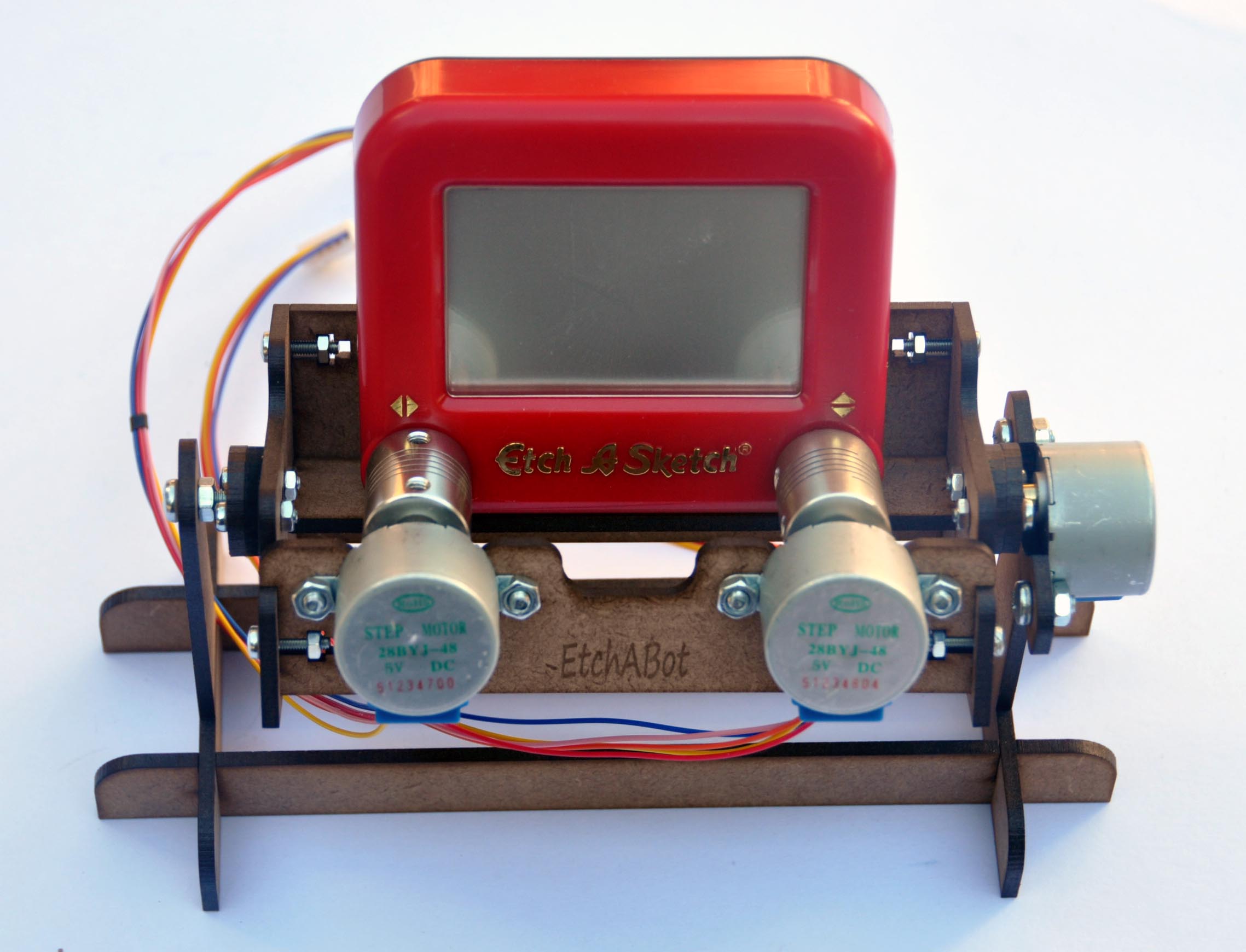
My project is a Segway clone, the progress can be followed at:
https://www.facebook.com/groups/1415442618700681/
All my sketches are based on the excellent work presented by Geekmom!
Thank you, and good luck on your project!
Hi
First of all thank you for your contribution, I really appreciated. I use the code with DMP but as ALDO mentioned takes several seconds to stabilize and when its done, the value start to drop very slowly, is this ok? Im refering to the ypr[0] value (the 1 and 2 gets to 0.xx), on this case value gets around 15.00 when calibrating then drops 14.99,14.98 and so on, takes around 1 sec on every value change.
Sample
DMP: -0.45 : -0.13 : 15.04
DMP: -0.45 : -0.13 : 15.04
DMP: -0.45 : -0.13 : 15.03
DMP: -0.45 : -0.13 : 15.04
DMP: -0.45 : -0.13 : 15.03
DMP: -0.46 : -0.13 : 15.03
DMP: -0.46 : -0.13 : 15.03
DMP: -0.46 : -0.13 : 15.03
DMP: -0.46 : -0.13 : 15.03
DMP: -0.46 : -0.13 : 15.03
DMP: -0.46 : -0.13 : 15.03
DMP: -0.46 : -0.13 : 15.03
DMP: -0.46 : -0.13 : 15.03
DMP: -0.46 : -0.12 : 15.03
DMP: -0.46 : -0.12 : 15.03
Also, I remember that my breakout board do turn the included led on on green color, now is red,any ideas?
Thank you
Hi,
I don’t know about the light on the breakout board – I haven’t noticed that on mine. I do think it’s difficult to get rid of all Yaw drift, though, so it’s probably normal that you’re seeing a slight drift after the initial calibration period. Are you sure to keep the MPU6050 steady for the first 10 or so seconds so that it can correctly calibrate the Yaw drift?
Debra
My sensor has the red light too; I think just a new choosed colour by builders 🙂
Hi
Yes, sensor is inserted on a mini protoboard static on a table. Do you think that zeroing values after calibration is done can be applied without affecting it?
Regards
Thanks ,
please how can i save MPU6050 datas to matlab worspace
Hi,
My results showed FiFo overflow. Will that actually effect the values in someway i.e less accurate?
That’s a good question. I was actually not sure what happens to the data in case of a FIFO buffer overflow, so I just looked it up. According to the Invensense documentation at: http://invensense.com/mems/gyro/documents/RM-MPU-6000A.pdf (see page 45), when the buffer overflows the oldest data will be discarded and the new data will still be written to the buffer – so the oldest unread data gets lost. If you’re not concerned with collecting all of the data – and you just want the most recent, the overflow may not be a big problem for you. Buffer overflows make me nervous, however, and if you wish to avoid them, you can slow down the DMP FIFO buffer write rate with the method mentioned in the article.
Thank you so much for the response. As a matter of fact, I do need to collect all the data for my gait analysis project. I will try to slow down the DMP FIFO buffer as you mentioned. Thanks again!
Hi Geek mom,
You have been the biggest help for my project, I could not have made it this far without your blog.
I have one question though, whenever I use The DMP, my yaw behaves weirdly.
when the MPU 6050 is flat on the surface, the Yaw readings are correct and act normal, However when the pitch or roll increase, the yaw will change automatically, tending to zero, is this to be expected? and is there a way to solve this issue?
Thank you very much
I haven’t observed the behavior you mention, I’m afraid. For the first 8-10 seconds the yaw drifts while the DMP calibrates, so you should keep the MPU6050 still during that time period. If you are observing it after that time period, then I’m not sure what might be causing it.
That’s weird, because without using the DMP, the yaw is fine (except for the drift issues), and my project requires me to make head tracker which can be used in gaming, so YAW is essential.
I guess i have to buy a new breakout board and check if the issue is still there.
Thanks again for your help 🙂
Good day Geek Mom!
I’ve followed your instruction in fixing the line 305 of the h file to prevent the FIFO overflow, but it still happens all the time. I’m using it to communicate with Simulink, and from the data I can see that the FIFO overflow occurs every 350 ms. I also have tried to change the TWBR to 12, but nothing changed. Do you have any idea to fix this?
Almost forgot, I don’t use the interrupt pin in the wiring. I only use SDA SCL VCC GND. Is it okay, or is it the source of the problem?
Regards,
Ryan
You have to use the interrupt pin if you are retrieving data from the DMP using this example. The code to read the DMP looks for the interrupt as a signal that there is data available to be read. I’m not sure exactly how the code will react if you leave it out, but I’m pretty sure it’s important.
I used a similar (if not the same) code example for the MPU 6050 by Jeff Rowberg and found that you can get away with not using the interrupt pin if you have to (as I did because that pin is used by the MotoProto motor shield on my Arduino setup and I didn’t want to hack the shield (yet…)). You do have to alter the code a bit, (takeout the setting of the interrupt handler and modify the inner code loop so that it reads and then checks the fifocount and then break out if the fifocount is big enough to contain a ‘packet’).
Not entirely sure this is completely kosher, but so far it seems to work OK. I found that the inner loop went around about 13 times before the fifo had enough in it to cause the breakout. However if you were doing much in that loop, you might have issues with this ‘polling’ method and it is inefficient anyway, having to continuously read the i2c to get the fifo count.
Hi Debra,
do you know how to calibrate accelerometer? I did few tries but with no success. I read comments on this post and two people suggested how to do this, but it’s not working for me. Without calibration the complementary filter seems to work fine. Did you try to do calibration for accelerometer later as well? Thank you
Initializing I2C devices…
Testing device connections…
MPU6050 connection successful
Initializing DMP…
Enabling DMP…
Enabling interrupt detection (Arduino external interrupt 0)…
DMP ready! Waiting for first interrupt…
help please any suggestion,i’ve waited too long but nothing happens.
Hi had the same problem. The solution is quite easy, you just forgot to link both interrupt-pin’s. On Arduino mega it’s Pin 2, so should have to use 5 jumpers then.
hello my name is Dipty,
can you help me?
i have a problem while download the program on processing
it written “ArrayIndexOutOfBoundsException : 1”
so what should I do?
thanks
It’s probably a problem in the Processing program where it’s getting a list of the Serial ports. On my computer the serial port was the 2nd port in the list. Try changing the index in the serial port list to 0 instead of 1.
okay thanks
but when it is running why the complementary filter didn’t work?
why it still at 0 when i run the program on processing?
thanks
Are you seeing the DMP data?
yes but the complementary still at 0
There could be lots of reasons. First you need to figure out if the data is correct when it is coming from the Arduino sketch. It would help to see what the data looks like. You should try running the Arduino sketch and just sending the data to an Arduino IDE serial window. What do you see in the serial window?
i also have same problem. I have serial monitor the data from arduino IDE. the complimentary is 0. DMP data works fine.
If you look at the Arduino output, I think you should see a specific error if the FIFO buffer is overflowing. If you’re just seeing 0 for the values, it might be something else. Sometime in the next few days, I’ll dig out my GY-521 and see if I can reproduce the error.
Thank you for this article!
I am experiencing some issues sending the gyro output data over bluetooth, anyway. I am using an HC-06. Everything works flawlessly reading the data from the cabled serial, but on the bluetooth one i have some random freezes (lasting 0.1 / 0.2 seconds each moreless). Disabling the filter seems to remove them. I have increased the baud rate to 115200, and of course i have edited the .h file in order to avoid overflows. I have no clue about the cause 🙁
Hmmm, I’m afraid I don’t know – it certainly sounds like a buffer overflow. When I have time in the next few days, i’ll dig out my GY-521 and see if I can reproduce the problem.
Hello, I tried to use the DMP6 code, but when I compile it, I get the following error :
C:\Program Files (x86)\Arduino\libraries\I2Cdev/I2Cdev.h:37:20: fatal error: em_cmu.h: No such file or directory
#include
I don’t know where this file (em_cmu.h) is located and I can’t have the code running.
Can you please help me?
Grateful.
Hello, thanks for your share. But i have a problem. In the Arduino sketch, the values of CMP always 0. And in the Processing, complementary filter didn’t work! Do you help me fix it?
Many thanks!
Great post.
I’m working on MPU6050 library for ESP8266 and your articles are useful to me.
Thank you for sharing your experiments.
Hi.
Great work.
But I can’t find or do not understand, how can I read all data as 0-360 degree (in your code only seem yaw)?
Thanks.
I had some issues using the DMP on an ESP8266 Wemos D1 mini. Finally it is working (Link to issue below)! I had also to modify some lines of the code above “mpu_6050_i2cdevlib.ino” to make it work on my ESP8266, see link below! Also added the line println(Serial.list()); to the Processing sketch, to list in first instance all serial ports and than changed the “portIndex” according to the port number to which my ESP8266 is connected (In my case portIndex 32).
https://github.com/jrowberg/i2cdevlib/issues/426
I am really thankful that you provide all those tutorials they are very informative and useful.
Just amazing, thanks a lot.
Hello,
I have no idea why the processing sketch doesn’t work at all, it’s like there is no link between the processing sketch and the arduino sketch at all (the arduino sketch works fine with the data of both complementary filter and DMP showed on the serial monitor but its duration is random between half to 3 minutes).
Does anyone know what is happening? is it because i am using the latest version of processing program?
Thanks.