After completing the Programmable LED Sweatshirt project with the Arduino LilyPad. I was intrigued by the idea of a soft-circuit LED array that could be used as a scrolling message board and general purpose display. With Halloween coming up, my son and I decided to make our own costumes. We came up with the idea of a T-shirt containing an LED array that could scroll messages and display simple graphics.
Once we got the basic LED array working, we decided to add a small joystick to make our project interactive.
We used the following supplies for the basic LED Array:
- Arduino Lilypad 328 Main Board as a controller
- Rechargeable Lithium Polymer Battery
- Lilypad Simple Power Board
- 50 LilyPad LEDs (we used 48, but they come in 5-packs)
- FTDI Breakout board(for programming the Lilypad)
- Mini USB connector (to connect the FTDI board to the computer)
- Conductive thread (we went through several bobbins full, and could probably have ordered a larger spool)
- Needle with a large eye to hold the conductive thread
- A sharpie
- Fabric to hold the LED Array (we chose medium-weight denim to make sure it was thin enough to sew easily, but thick enough to prevent short-circuiting through the fabric).
- Thin black fabric to sew over the array, so that we can see the lights flashing, but hide the circuitry.
- Fabric glue
- Inexpensive t-shirts (Target!)
- Black Velcro to attach the LED Array fabric, thin cover fabric, and T-shirt together.
We used the following supplies to attach the joystick to the LED Array:
- Sparkfun Thumb Joystick
- Sparkfun Breakout Board for Thumb Joystick
- Breakaway headers to connect the cable to the Joystick Breakout Board
- 5-pin connector and cable to connect the joystick to the Lilypad (the connector we purchased came with both male and female connectors. We only used the female half)
- Soldering iron and fine-gage solder (to connect the joystick and breakaway headers to the breakout board)
- wire cutter to strip the ends of the connector so they could be sewn into the project
Instead of sewing the array directly to the t-shirt, we decided to sew the array onto a fabric panel that could be attached to the front of the t-shirt with Velcro. It’s much easier to sew onto a flat fabric panel than a curved t-shirt, and this allows us to remove the panel and use it in other projects as well.
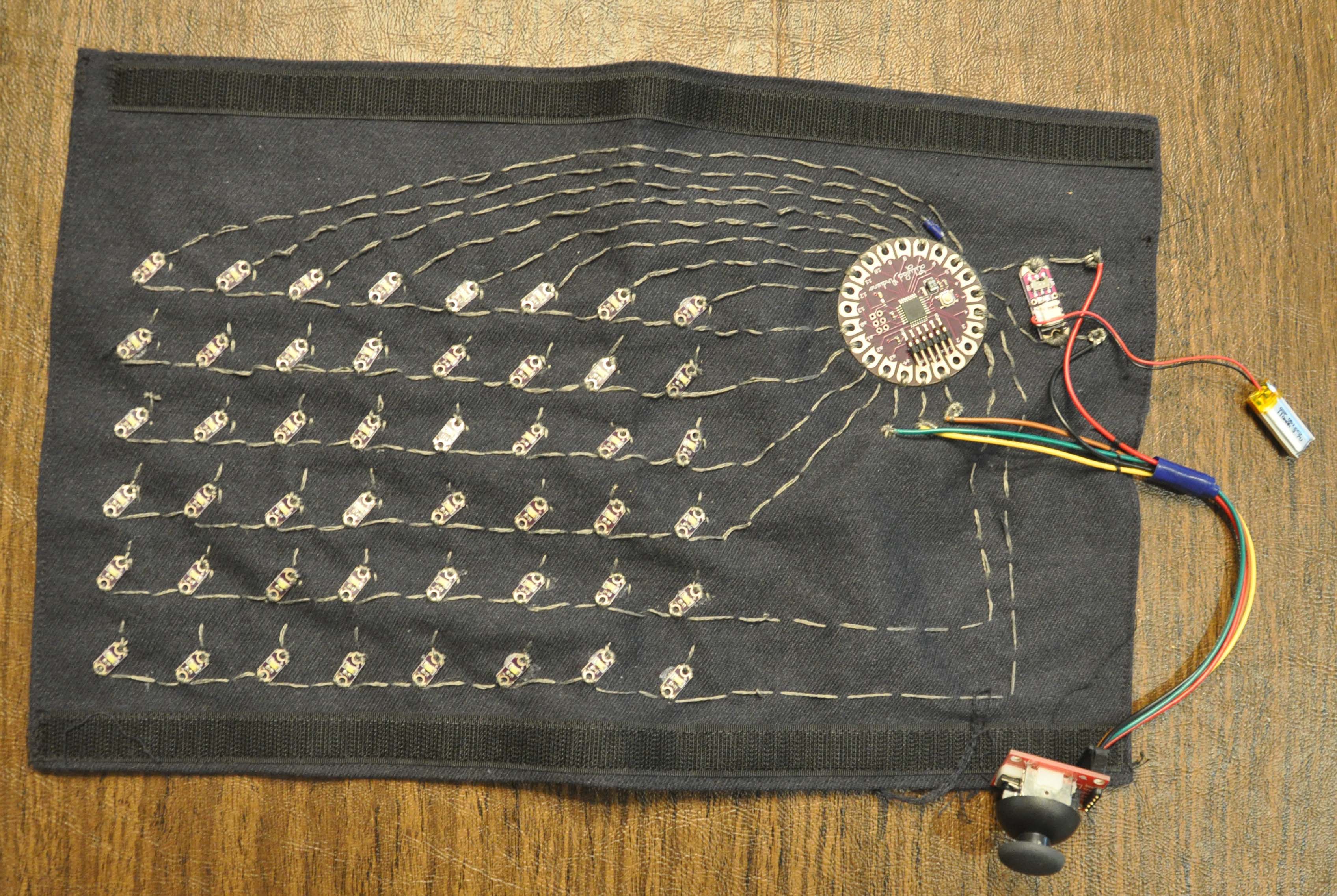
We decided that an 8 x 6 LED array would be manageable. The Arduino LilyPad has only 20 output pins, so controlling all 48 LEDs individually requires a technique called “multiplexing”. There are several different multiplexing methods that allow control of multiple LEDs by a smaller number of outputs. The method we used required that we sew all of the LED cathodes together in rows and connect all of the LED anodes in columns. To turn on a particular LED in the array, we set its row voltage low (ground) and column voltage high. The trick with multiplexing is that, unless the LEDs are in the same row or column, you can only turn on one LED at a time. If you attempt to turn on two LEDs that are in different rows and columns at once, you will end up turning on additional LEDs unintentionally. To get around this problem we take advantage of a phenomenon called “persistence of vision”. The human eye will retain the last image it has seen for some period of time, so flashing a pattern of individual LEDs on rapidly and repeatedly in a sequence will create the appearance of the entire pattern being illuminated at once.
Here are the steps in the construction process:
Step 1 – Marking Out the LED Array:
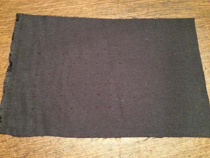
To keep the array neat, we marked out the positions of the LEDs with a ruler, and cut a piece of denim fabric large enough to hold them. I went for a 1-inch spacing between LEDs. When my son did his, we opted for 3/4 inch spacing, which I think looks neater, but since the rows and columns are closer together, it makes it harder to avoid short circuits.
Step 2 – Adding the LEDs:
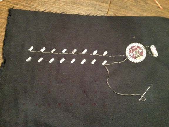
Using fabric glue, we lightly glued down the first two rows of LEDs, so that they would stay in place while sewing them. We took care to align the LEDs at a 45 degree angle to help avoid crossing threads when sewing the columns and rows. We opted to orient the positive sides of the LEDs up for the columns and negative sides of the LEDs downwards for the rows.
Step 3 – Sewing:
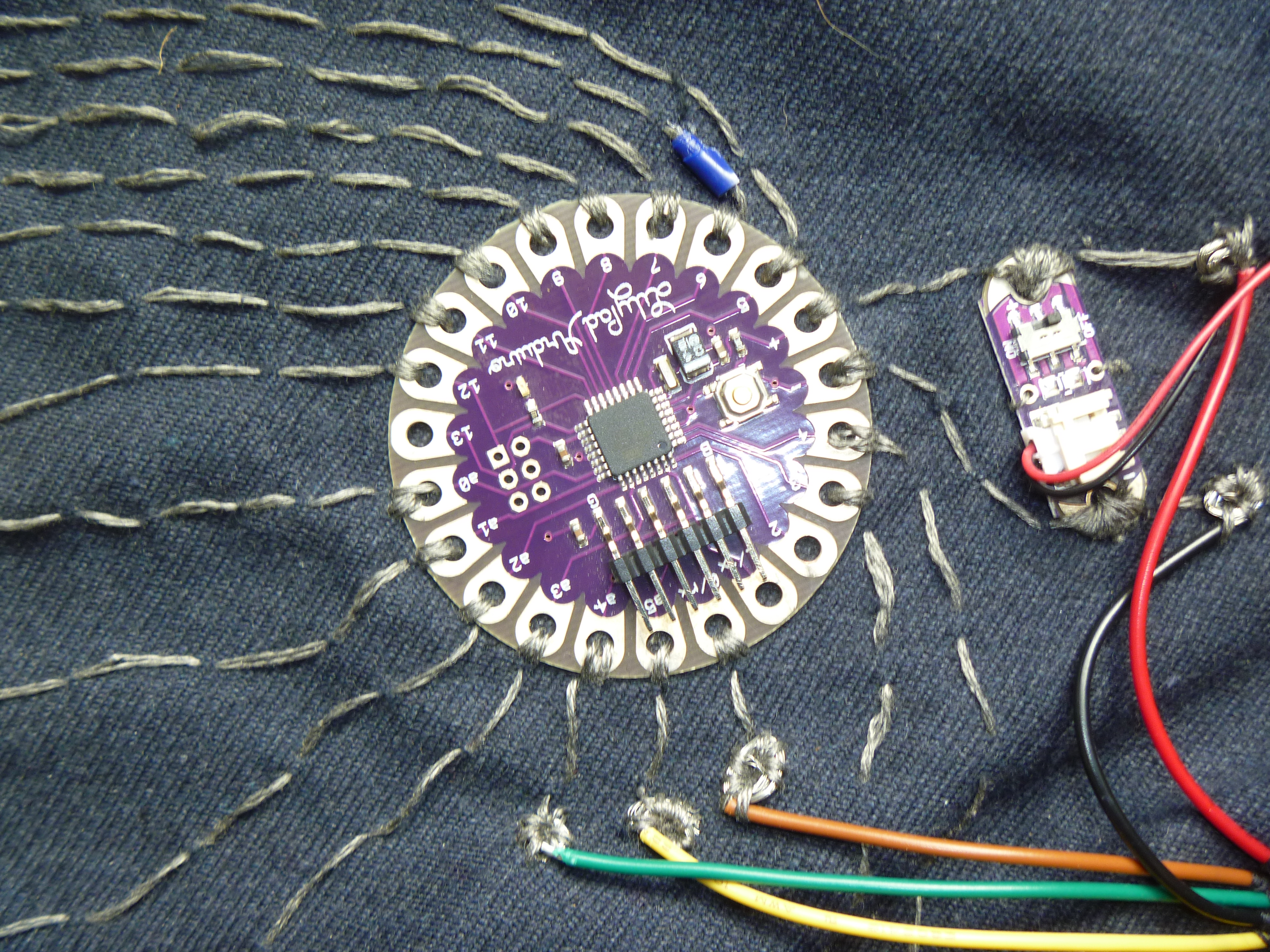
We started sewing the first two rows with the conductive thread – looping several times through each LED anode to ensure a good connection. We also attached the power supply to the “+” and “-” pins on the Arduino. The conductive thread is fairly thick, so we used a needle with a large eye. We used a simple stitch to sew the rows primarily on the top side of the fabric, planning to cross the columns under the rows to avoid short circuits. When tying off the thread at the end of a row or column, I tied a small knot and used a drop of fabric glue on the knot, so I could trim the thread close to the knot without risk of it unraveling. Before sewing the rest of the rows, we sewed two columns and ran a test on the completed circuits containing four LEDs. The test worked well, so we glued the rest of the LEDs and sewed the rest of the columns. I wrote a simple program to turn each LED on in turn, and we periodically tested the LEDs as we sewed to make sure the connections were good and there were no short circuits. We sewed the power supply board with the LiPo battery to the fabric, and sewed the connection to the Arduino LilyPad. We wound up using pins {A0, A1, A2, A3, 3, 4} for the anodes (columns) and pins {5, 6, 7, 8, 9, 10, 11, 12, 13} for the cathodes (rows).
|
|
|

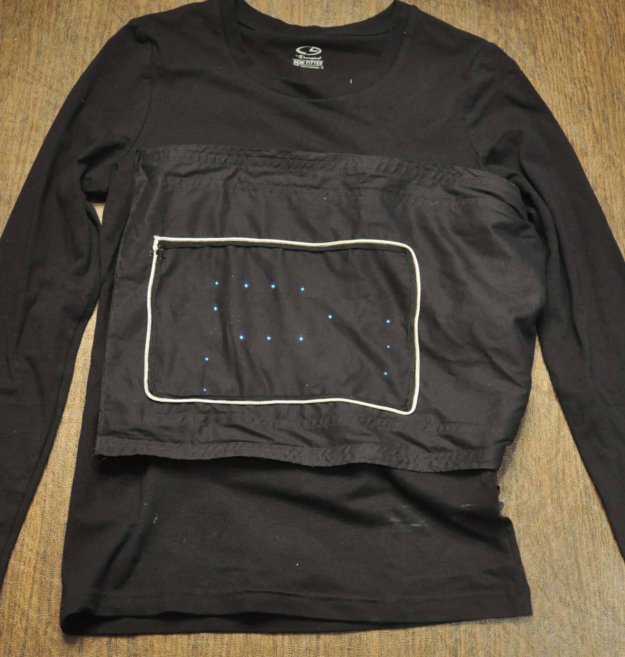
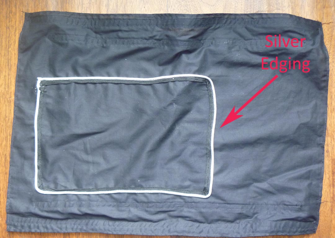
Up until now, we’d done all sewing by hand with needle and thread. For this next part, I brought out my sewing machine. After all of the circuits were sewn onto the denim fabric panel, I hemmed the edges of the panel for neatness, and sewed Velcro strips along the top and bottom edge of the front of the denim fabric. I then sewed a cover panel for the LED array out of sheer black fabric, attaching two sets of Velcro strips to the cover panel to hook into the Velcro on the LED array. This allows the LEDs to shine through the cover panel while concealing the circuitry. I happened to have some silver edging in my sewing box, so I sewed a rectangular “window” on the cover panel around the area covering the LEDs. This emphasized the LED panel and gave it some visible boundaries.
|
|
|
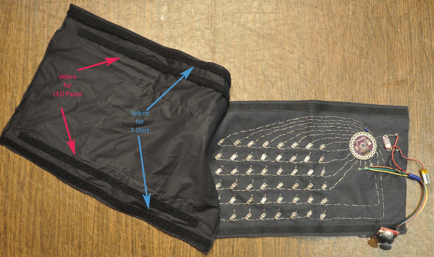
Finally, I sewed additional strips of Velcro to both the cover panel and the T-shirt so that they could be attached together.
Step 4 – The Joystick:
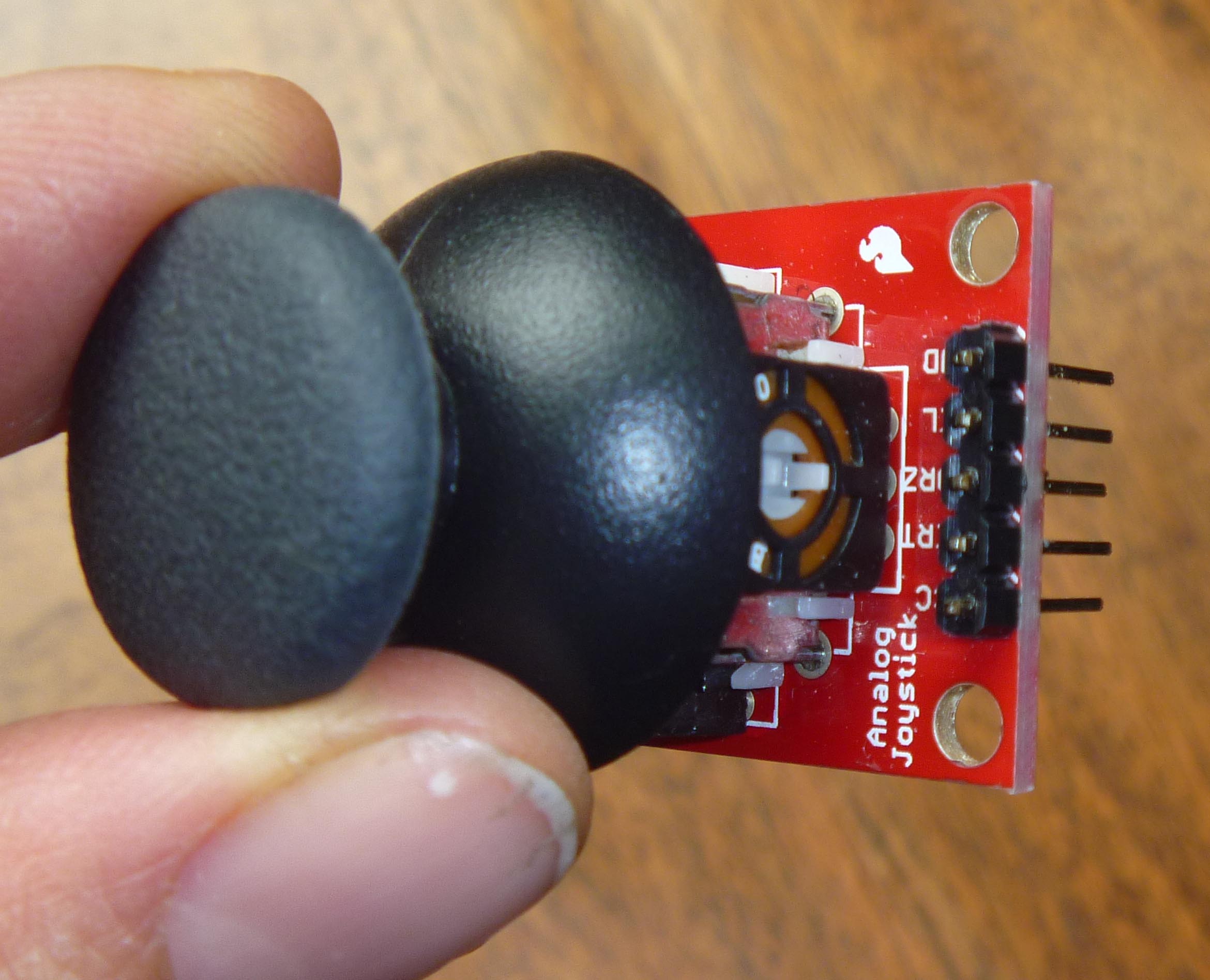
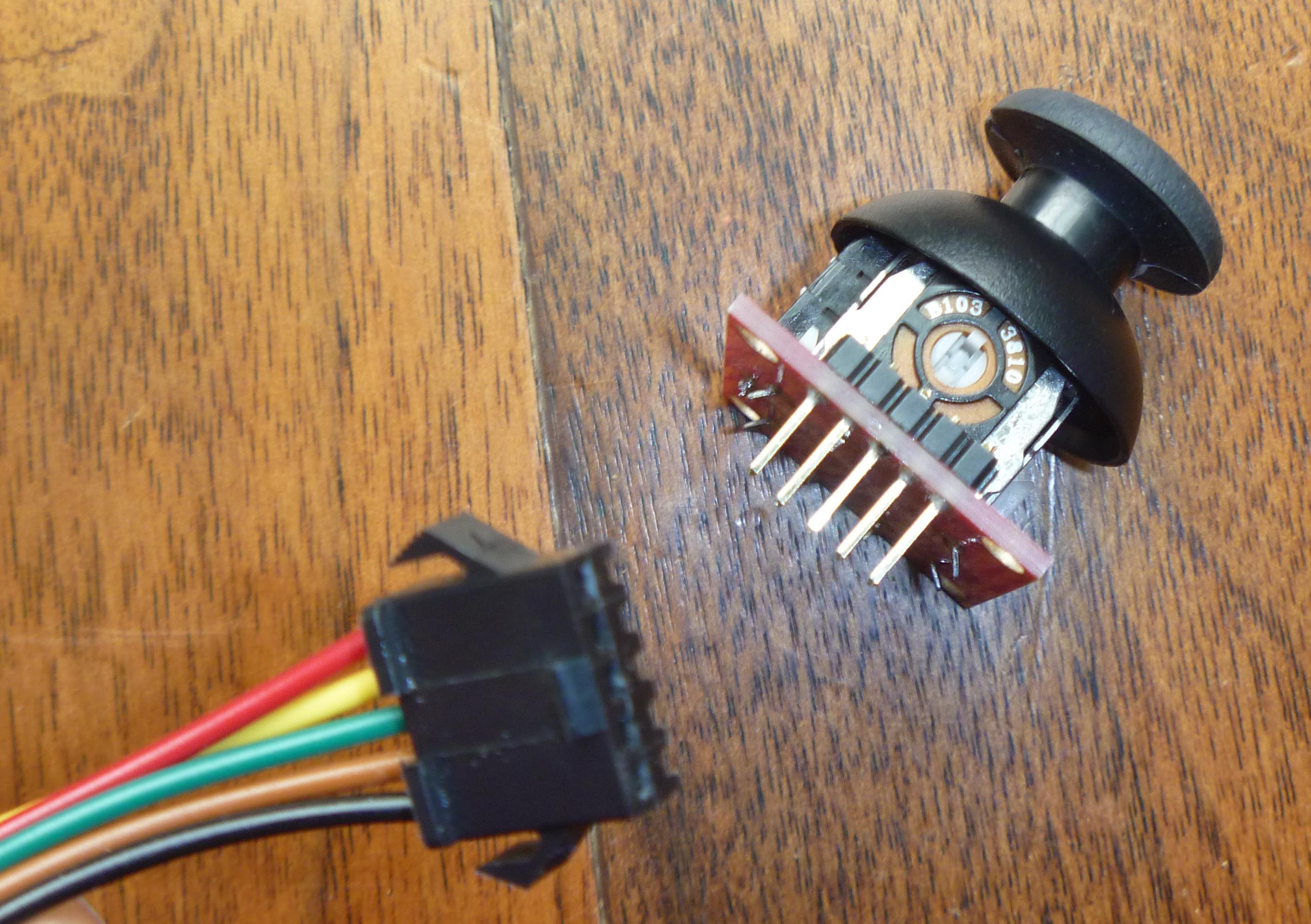
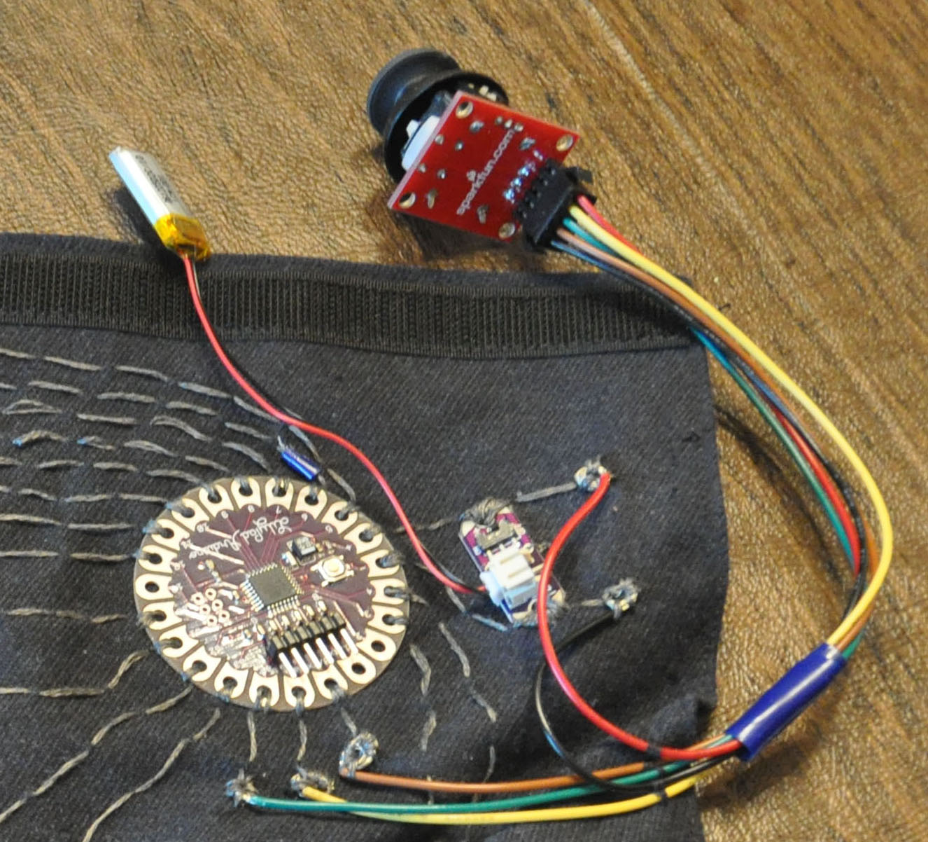
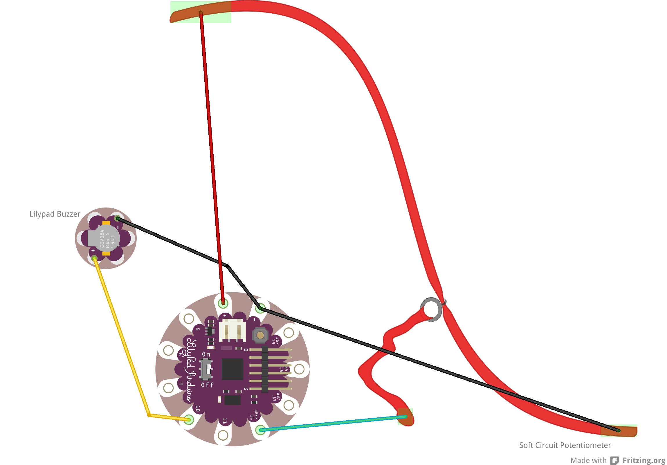
Once the LEDs and power supply were in place, we decided that we could make games if we had a controller, so we found a small joystick, the Sparkfun Thumb Joystick, with two discrete directions and a center button. To make it easier to attach to the shirt, we soldered it to the Sparkfun Breakout Board for Thumb Joystick. Then we had to figure out how to attach the joystick breakout board to the LilyPad. We didn’t want to sew the joystick directly to the shirt, but rather leave it attached by wires for accessibility, and so that the wearer wouldn’t end up getting groped by someone who wanted to play games with the shirt. We searched around until we found a 5-pin cable to attach to the 5 pins of the breakout board. (The 5 pins represent power, ground, xpos, ypos and button pressed). To make sure we could read the full range of x and y positions, we attached the x and y position inputs to the analog inputs on the LilyPad (the digital inputs can only read HIGH or LOW as an input). The 5-pin cable had a female connector, so we soldered 5 breakaway header pins to the female outputs on the breakout board. The connector then attached snugly to the header pins. We stripped the wires on the other end of the 5-pin cable, and rolled them into small loops (see picture below) and sewed them to the shirt, then connected them to appropriate output pins on the power board and LilyPad with conductive thread. We attached the joystick button to Pin 0, the x controller to Pin A4 an the y controller to Pin A5. In the programming we wound up polling Pins 0, A4 and A5 for input in the main loop. I found out later that the Arduino LilyPad has hardware interrupts on Pins 2 and 3, so if I did this project again, I might have used a hardware interrupt to process button pushes.
|
|
|
Step 5 – Coding:
Once all of the sewing/wiring was complete, it was time to program our LED matrix. We definitely wanted to be able to scroll text, and also add some games or animations that would look good at the relatively low 8×6 resolution. In the end, we made a game of “Pong” which worked in either automatic or interactive mode, a simple game of “Snake” and a feature that allowed the shirt to display the phrase “Ask me a question”, and then display “Yes” or “No” depending on which way the joystick was pressed.
Programming an Arduino board is easiest with the Arduino IDE Software. I wrote the code in C++, intending to create a base class with some basic matrix display properties and to handle the multiplexing, and create a child class for each game function of the shirt. To make scrolling text work, I found a low-resolution 5×5 font here. My object-oriented methodology could be better, but it works.
The code contains a chooser function that allows the user to select which feature to run, and the looping function (standard in Arduino) polls the joystick for button presses to toggle the chooser. If no button is pressed, it loops through whichever led matrix game/feature is being run at the time. You can download the code I wrote from this link:
Step 6 – The Final Result:
nice 🙂
How many leds did you connect in serie??
By the way nice project dude.
Your project has been included in the article: “20 Arduino projects of 2013″ – http://www.nudatech.com/blog/20-arduino-projects-of-2013/
Can I have the code of displaying text with using the joystick?
That code is part of the Arduino sketch at the bottom of this post. Let me know if you have issues downloading it.
I would like to Design a game (can be an existing game) that can be played on an arduino powered t-shirt. will be the same idea as you. could you help me please.