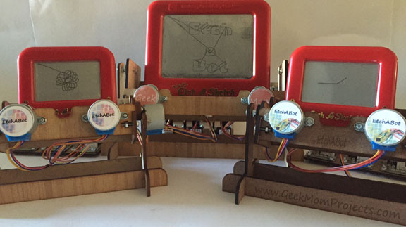
I found a YouTube video of a clock that can draw the time with an erasable pen, then wipe it away before restarting the cycle:
There is something very human and endearing about the motion of the arms as they perform their task of drawing and erasing over and over and over again. After locating the plans and instructions by joo at Thingiverse, I absolutely had to make one.
The Plans:
Joo provided PDF plans for laser-cut parts along with a 3D Google Sketchup file of the assembled machine. There is also a 3D printable version of the plans. I uploaded the design to Ponoko, an online on-demand manufacturing service, to be laser-cut from 3mm clear acrylic and shipped to me. Before uploading it, I imported the PDF design file into Inkscape (a free CAD program) to modify the line thickness and color to fit the guidelines [line color = blue, line thickness = 0.1 pixel] for Ponoko uploads. I then saved it as a SVG (scalable vector graphics) file. The upload and ordering process was very easy. The hardest part was waiting for the package to arrive.
In addition to the laser-cut parts, there are instructions for 3D printing a holder/sweeper for the pen. The original design used the pen’s own cap with a small piece of cloth attached by double-sided tape for erasing. I couldn’t find model of dry-erase pen that Joo used anywhere in the United States, so I printed the cap from the file provided, and ordered a few different models of dry-erase pens online, hoping that one would work.
Assembly:
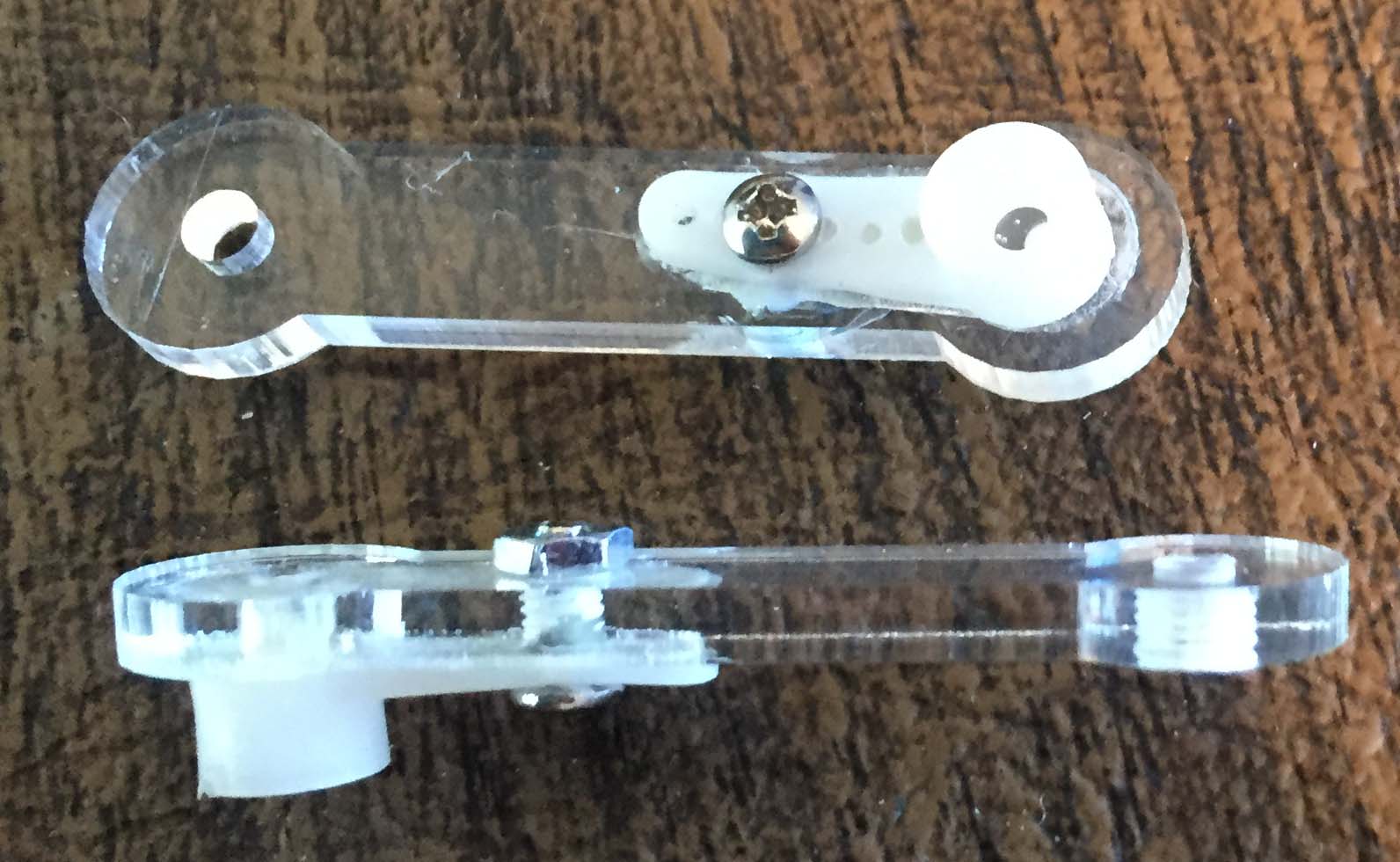
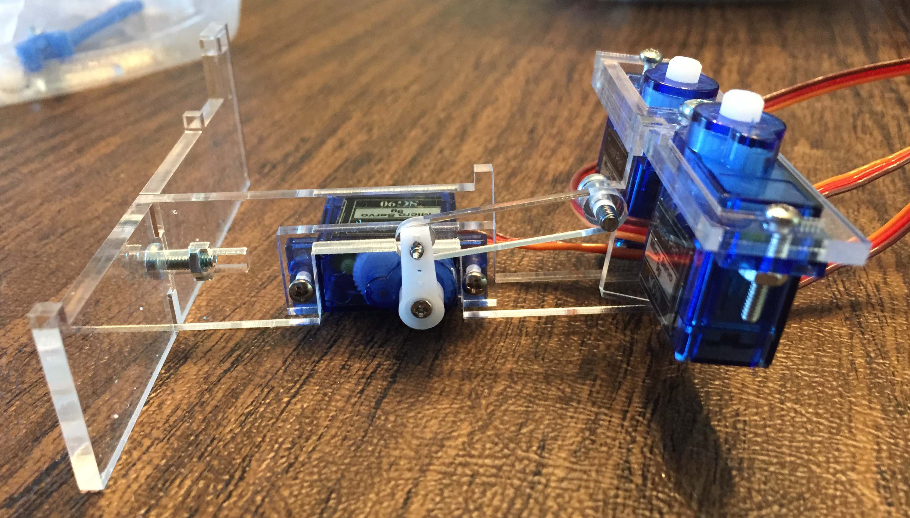
The PlotClock design is ingenious, and the instructions on Thingiverse are pretty clear. However, the assembly was still a little tricky. The Google Sketchup 3D model was extremely helpful in viewing the relative orientation of the parts from any angle. I found that the arms that attach to the servo horns didn’t get a hole cut for the servo arm screw, so I had to drill one in each arm. To attach the arms to the servo horns, I glued the horns to the arms with plastic glue and let them dry overnight. I then drilled another hole for a 1/4″ long 2-56 screw to reinforce the join.
Some of the holes in the PlotClock parts are 3 mm in diameter and some are 2.5 mm in diameter. All of the 2.5 mm holes are intended to be tapped with an M3 tap. Most of the parts could be joined together with 10 mm long M3 screws and nuts, though I needed a 16 mm M3 screw to attach the piece holding the servos to the main body. The parts which need to pivot must be screwed together loosely enough that they are free to move.
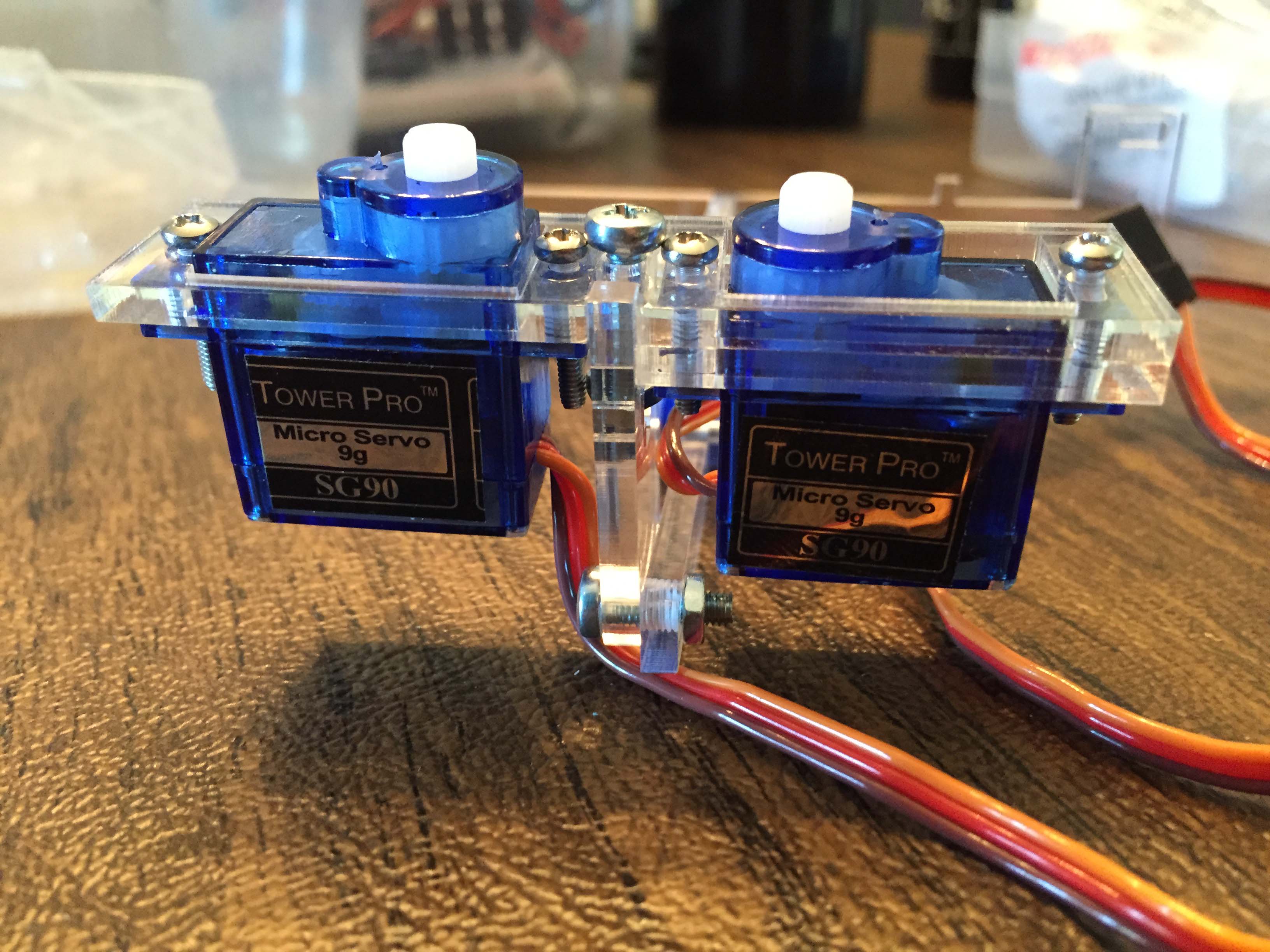
The holes for mounting the servos to the acrylic were not quite large enough for the 6-32 screws (the typical size for mounting 9g servos), so I had to drill the holes slightly larger before screwing the servos in place.
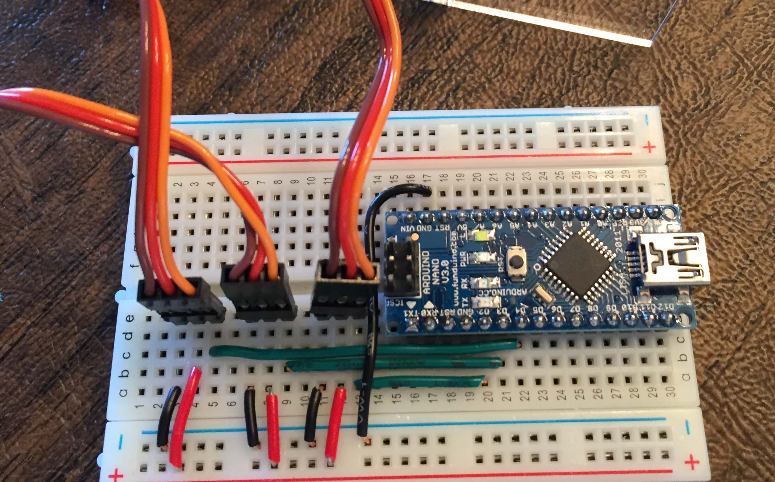
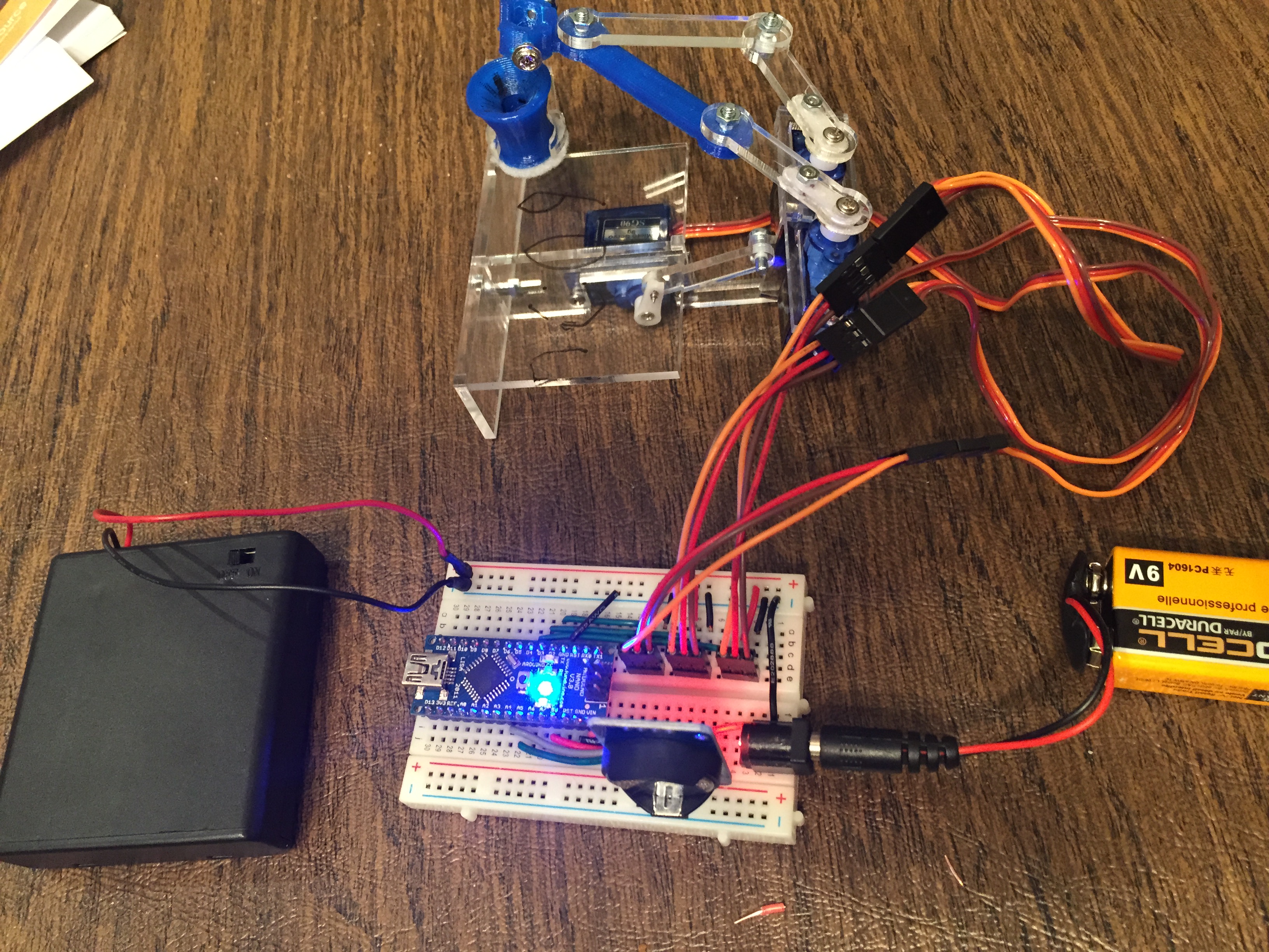
The electronics were controlled by an Arduino nano clone. Joo provided an Arduino sketch that can be used to calibrate the servos and run the PlotClock. The servos are controlled by Arduino pins 2, 3 and 4, though the specific pin numbers can be changed in the code. The servos get 6 Volts from a 4 “AA” Battery Box. The Arduino was powered separately with the USB computer port during testing. I have found that servos have less jitter when they have a separate power source.
Testing:
The PlotClock Arduino sketch has a calibration mode which can be activated by uncommenting a single line of code. In this mode you can adjust several numerical factors until the horns rotate back and forth exactly 90 degrees from vertical to horizontal. This was very helpful in getting the servo alignment right. In addition, I found it necessary to alter the factor that adjusts the height the pen is lifted to put it into the sweeper. The code is very well commented, so it was just a matter of trial and error to get values which worked with my setup.
I couldn’t get any of the pens to fit easily in the pen holder or the sweeper I’d 3D printed. Fortunately, another Thingiverse poster, CrazyChicken563, had posted an “upgrade” to PlotClock, which allowed it to use Expo brand fine tip markers. I printed a new arm to hold the pen, and a new sweeper with a larger, angled “mouth” to make it easier to replace the pen after drawing. The pen holder arm CrazyChicken563 posted on Thingiverse was designed to go on the right hand arm, so I 3D printed a mirror image of his design to work on the left side instead. A small circle of felt was affixed to the bottom of the sweeper with double-sided tape. The “upgrade” worked like a charm, though after several repetitions, the pen tends to slip upwards in the holder. I’ve fixed this by drilling and tapping holes in the side of the pen holder for short M3 screws to hold the pen in place.

Additionally, I found that the servo horn on the servo responsible for lifting the pen was just slightly too long and hit the drawing surface. Fixing this was simply a matter of of clipping the tip of the servo horn (see picture below):
Adding the Real Time Clock (RTC):
The PlotClock source code can read the time from a real time clock (RTC), which I added after the other parts were working. I ordered the DS3231 RTC from Ebay. It came without batteries, so I ordered some LIR3202 rechargeable batteries to go with it. The DS3231 is set up to recharge the batteries when connected to a power source, so it is important that you don’t use single-use batteries with it. Setting up the RTC is very easy. Here is a tutorial which explains the wiring and setup code. You need to download the DTC1307RTC library and run the example program that comes with it to set the time. After that, as long as you don’t remove the battery, the RTC will keep correct time for several years (though it will not keep daylight savings time as that varies regionally). Once the RTC is set correctly, you only need to uncomment one (easy to find) line of code in the Arduino sketch to get PlotClock to give you the correct time.
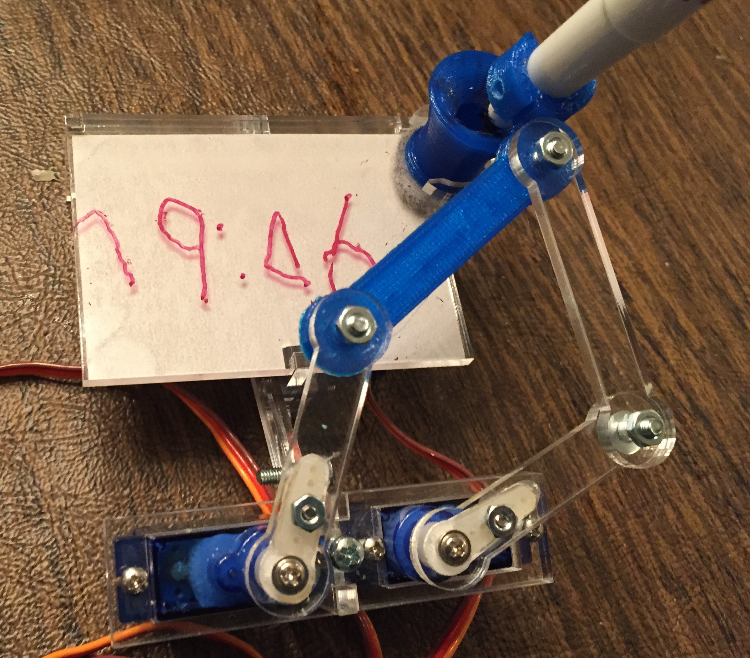
The Results:
Below are a couple videos showing PlotClock in action. The second video incorporates the RTC and the modifications to the pen clip to hold the dry-erase marker in place.
So very cool.
it’d be interesting to replace the laser cut bits with printed parts too. Lasers are so expensive.
Have everything set up and working now. However I was wondering if there is a way to make the clock write the numbers upsidedown (the thought is to have it up on the wall with the arms hanging downwards). And in it´s current shape that will make the time being written upside down 🙂 Any ideas?
Looking at the PlotClock Arduino code, I think that inverting the text would be very difficult to do as the coordinates are not easily parameterized. Good luck to you if you decide to try, though.
Maybe this helps
http://www.thingiverse.com/thing:386449/#instructions
Is there a way to use a raspberry pi instead of the laptop? Thanks
The laptop is only necessary to program the Arduino. The code actually runs on an Arduino board. I’m not sure if your question was about substituting the Pi for the Laptop or for the Arduino. Either way it is possible. You can program an Arduino from a Raspberry Pi and you could run the Arduino code to move the servos from a Raspberry Pi as well. You’d have to find equivalent libraries to replace the Arduino Servo library and Real time clock libraries and you’d have to adapt the 3Volt logic of the Pi to the 5 Volts needed for the servos. So it would be a bit of a pain, but it is possible. I hope that answers your question.
Besides the arduino, 3d printed parts, servos motors and the pen what parts do you need for the build? thanks
Hi Dave,
Make sure you read the assembly instructions carefully on the Thingiverse site (http://www.thingiverse.com/thing:248009/#instructions) You’ll need m3 screws (I think I used 8 or 10 mm lenghts), and an m3 tap (I used this: http://www.amazon.com/Irwin-Tools-2712–Piece-Set/dp/B003K15EQG/ref=sr_1_2?ie=UTF8&qid=1426531828&sr=8-2&keywords=m3+tap) to tap the 2.5 mm holes. Also, make sure that you have the right dry-erase pen to fit the pen holder – there are a number of different kinds out there. If you are 3D printing rather than laser cutting your parts, you’ll need a surface for the pen to write on – I don’t think it will write well directly on the ABS. Laser-cut acrylic works well for a writing surface, but other smooth materials will as well. Also, I used a RTC (real time clock) chip so that it will always tell the right time without needing to connect to my laptop. This is optional but I like having it. I had to buy the LIR2032 battery separately for it. Other that that, just the usual breadboard wires, and I power the Arduino off of a single 9V battery, and the servos off of a 4x”AA” battery pack. Good luck with your build!
Final question!
Which size acrylic did you go for in Ponoko?
P1, P2 or P3? Thanks
I used the P1 template in 3mm acrylic. Good luck!
Hi,
Our pieces we ordered from Ponoko today arrived but it seems that for some reason they are too big. The the motors don’t fit snugly into the cases and the holes don’t align. We took the file straight off Thingiverse and sent it to Ponoko and they said we had to fit it into a template. I guess it worked right for you but do you know where we went wrong?
Thanks
That sounds quite frustrating. Before uploading the SVG to Ponoko, I imported the svg file into a Ponoko Inkscape template – available from the “Download P1, P2, P3 templates” link on this page: http://www.ponoko.com/starter-kits/inkscape. Did you do that step?
Debra
Hi again
One more question!
We are having problems getting the code to work on the servos motors. The calibration is happening we think but is weak and only happens on one or two of the motors. There is one servos that work well but the other are like they are trying to move but can’t. Maybe a battery problem? We used a 9V battery which was better than powering it off the computer.
Can you help us with the code and setup?
Thanks again,
Davy
Are you running the servos from a separate power supply than the Arduino? The servos draw a lot more current, and it’s generally a good idea to run them off of their own power supply. I don’t think the Arduino can supply enough current to run more than one servo effectively. I’ve had that problem in the past. I have a plug in 6V wall adapter for the servos, and just run the Arduino off of its own 9V battery. It’s a little easier to find a 5 Volt adapter than a 6 Volt adapter, but you will get better response from the servos if you use 6 Volts rather than 5.
Also, when using separate power supplies for Arduino and servos, remember to tie the grounds together.
Everything is going well code wise. No errors now. Can you walk us through the calibration?
Thanks
Hi Davy,
You mean the calibration of the servos, right? I have to go back and look at what I did, because I don’t remember off hand. I’ll post a response as soon as I have a chance to dig out the PlotClock. What I do remember, however, is that it’s not a precise algorithm for getting the calibration right – more of a bit of trial and error. Anyhow, I’ll get back to you about this when I get a chance.
Debra
having same problem in calibration, please mention calibrations value, reply quick i have to submit my project by tomorrow :((
It seems there are two components to be engraved (the black areas). One area contains two holes and one contains one hole. Is that on purpose and should I engrave it? I noticed you did not engrave.
The engraved parts are there to show you where to line up the servo horns. I can’t remember if I engraved there or not. The engraving is not necessary, though it does help with alignment. You could do it either way.