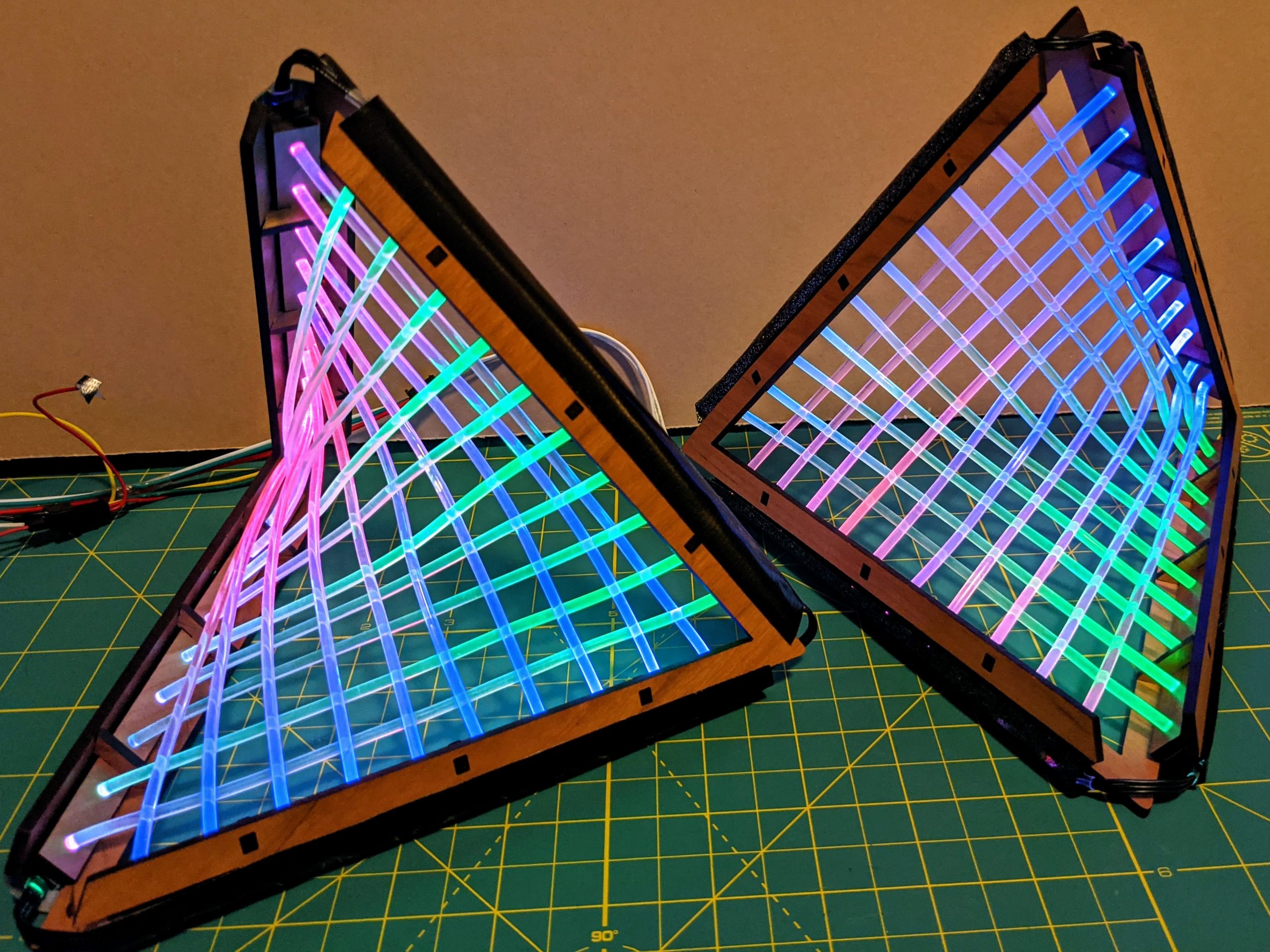
Ruled surfaces are mathematical shapes that can be generated by sweeping a straight line through three-dimensional space. A hyperbolic paraboloid is a “doubly ruled” surface which has two straight lines passing through any point on its surface. I was inspired to try to make an illuminated version of a hyperbolic paraboloid when I came across this Math Art blog post. The post shows how to construct a hyperbolic paraboloid from intersecting straight lines, using the fact that the straight lines in this surface may be formed by joining points along the edges of a tetrahedron.
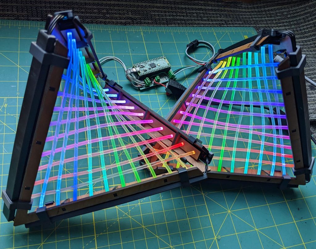
Note: I just updated this project with 3D printed covers and clips to hold the LED strips in place. Scroll to the end for the design files to print them.
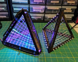
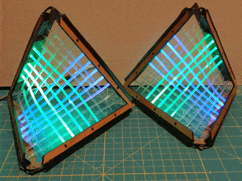
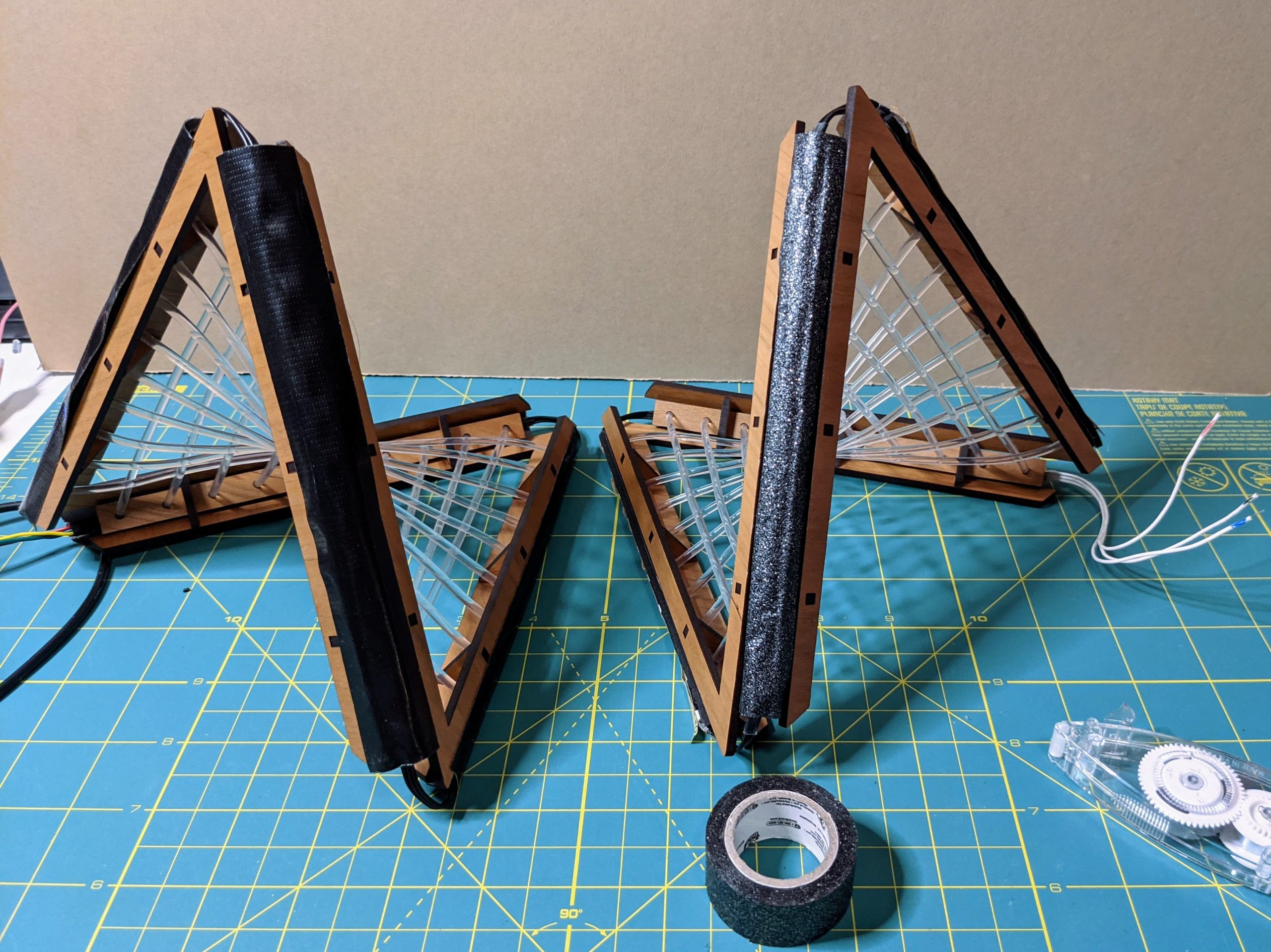
Early versions of this build (above) above used fiber optic cable to join edges of a laser-cut tetrahedral frame. It worked, however, two of the edges weren’t structurally necessary for the build and blocked the view of the fiber optics. The final version documented here removes the unneeded edges and creates a simple, aesthetically pleasing structure that works well to hold the fiber optics in place.
Below are the instructions to build this project yourself. It’s surprisingly straightforward project to build, even though it appears complex. You will need access to a laser cutter to cut out the frame pieces, however.
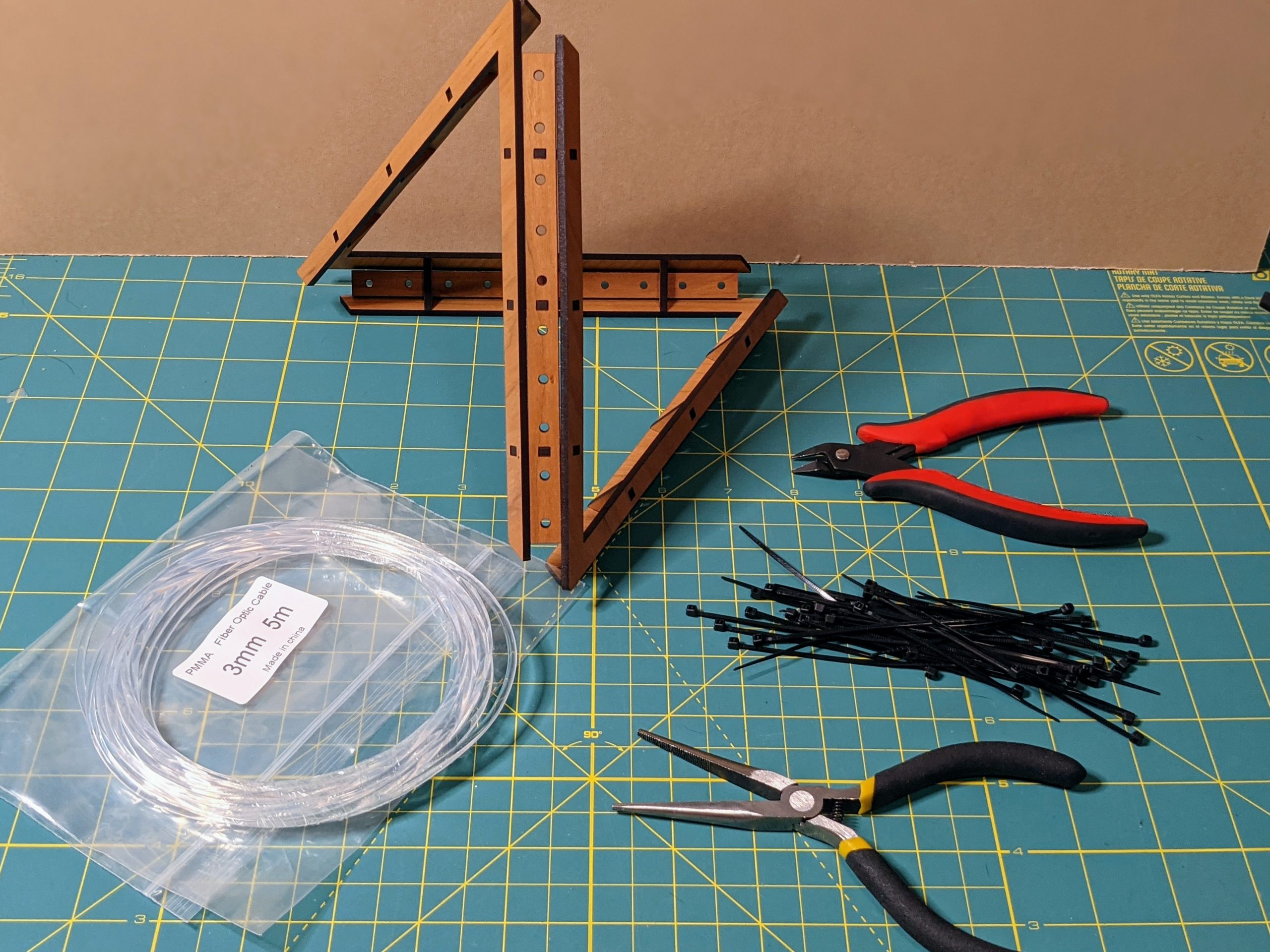
Materials
- 1/8″ (3.2mm) wood sheet for laser cutting
- 3mm thick EVA foam with an adhesive backing
- 40 small (2mm wide or similar) zip ties
- A little less than 15 feet of 3mm diameter solid-core side-glow fiber optic cable
- optional: wood glue
- Four 10-led lengths of a 60 LEDs/meter WS2812b LED strip containing 3535 sized LEDs, without any joins in the strips (if you use a strip with 5050 LEDs, you’ll need to make the squares in the EVA foam strip a bit wider to accommodate them)
- duct tape (1″ width is ideal, but you can trim a wider strip down)
- hookup wire/solder
- microcontroller for coding the patterns
— If you wish to 3D print covers for the LED strips instead of using duct tape, you will need a 3D printer and filament (PLA is fine)
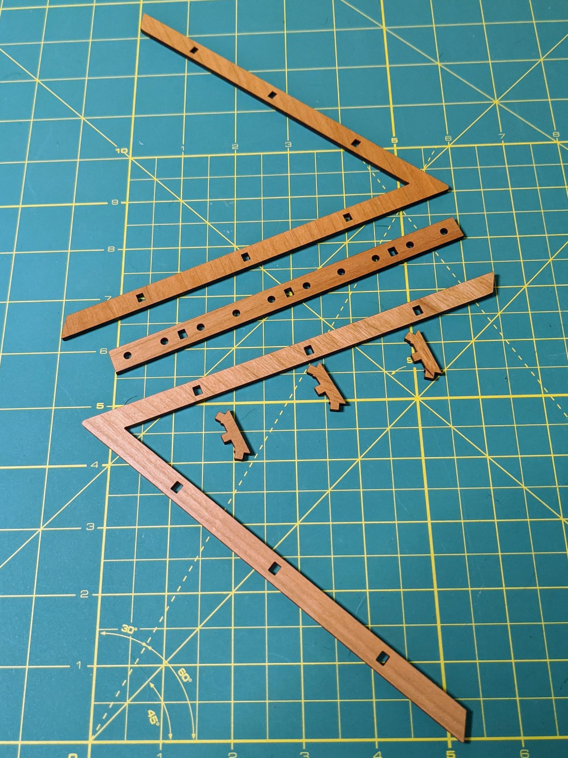
Laser Cut the Pieces
The vector files for the wood and EVA foam pieces can be found on my GitHub repository here: https://github.com/geekmomprojects/fiber-optic-hyperbolic-paraboloid.
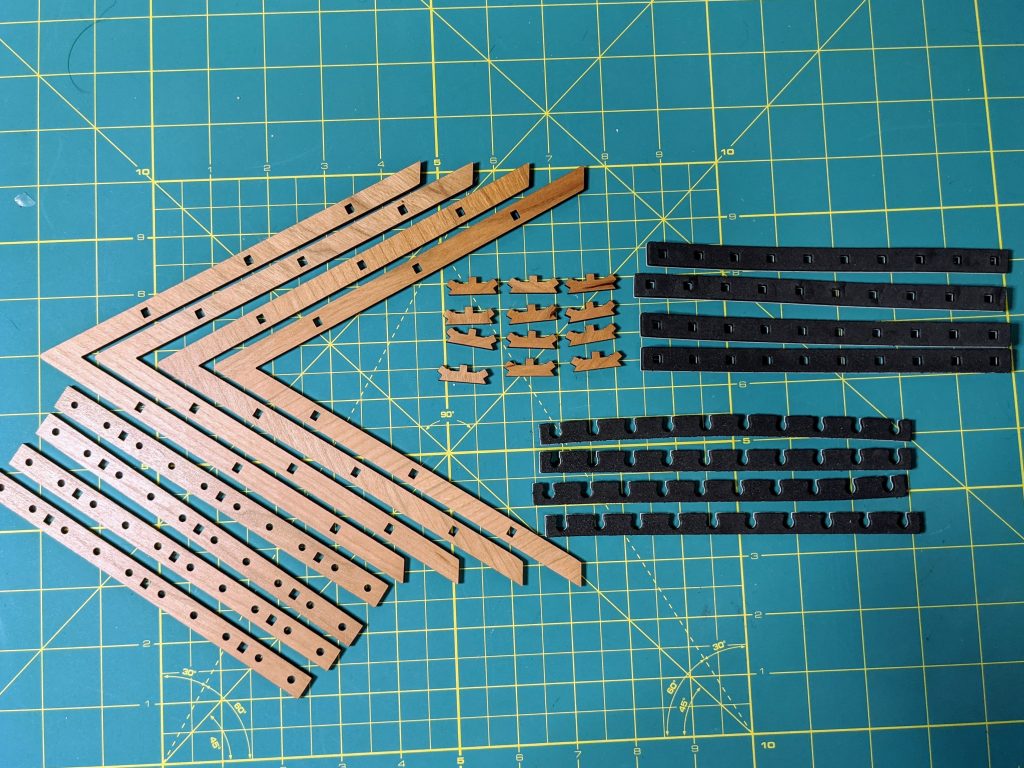
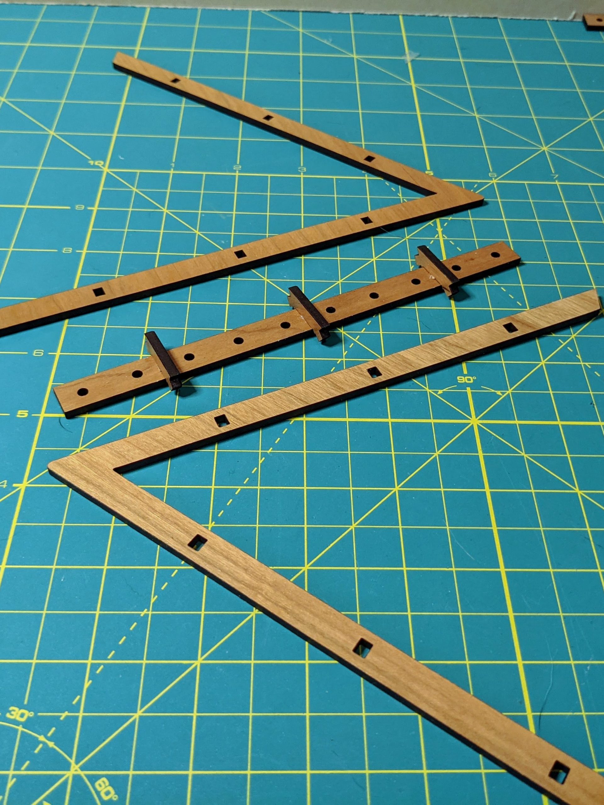
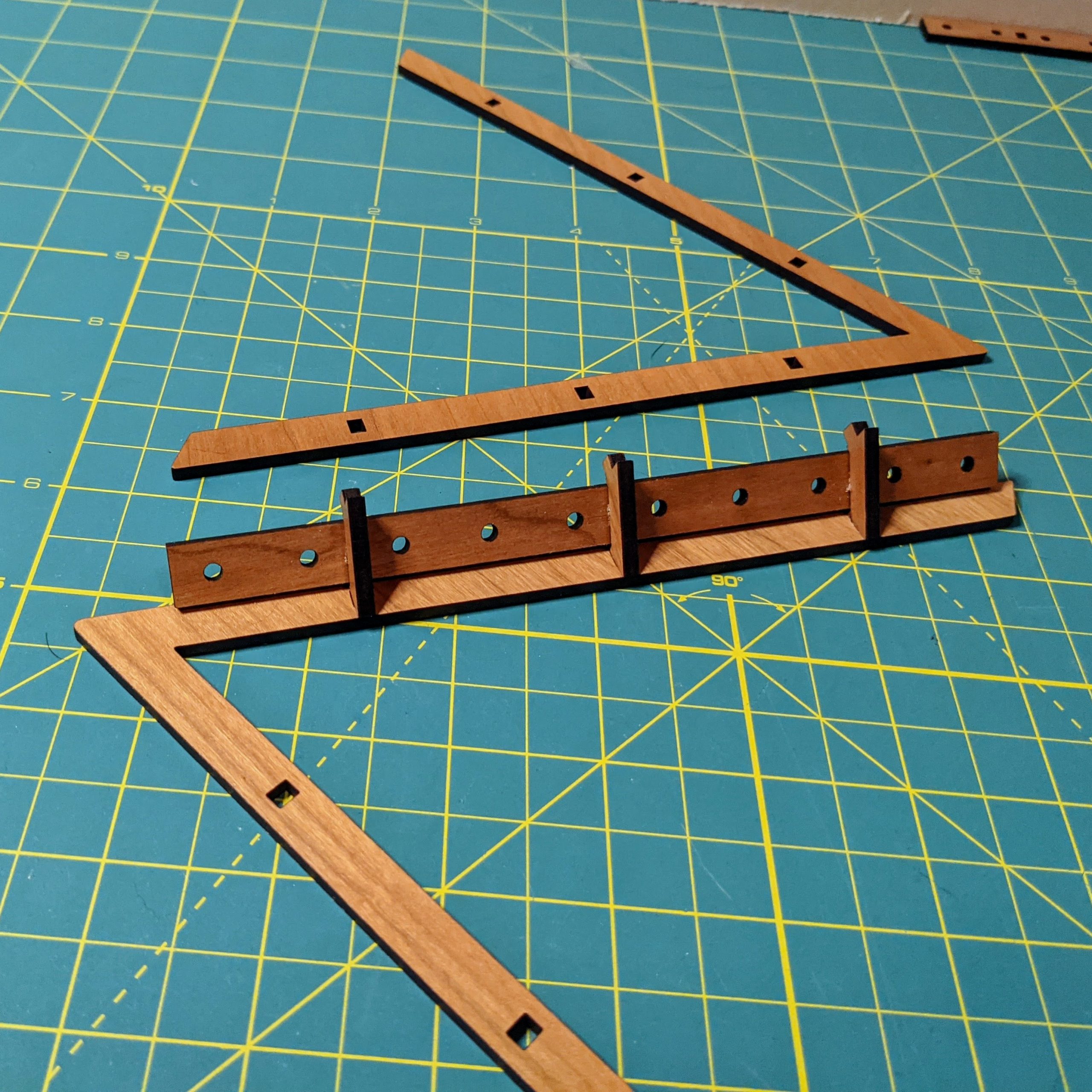
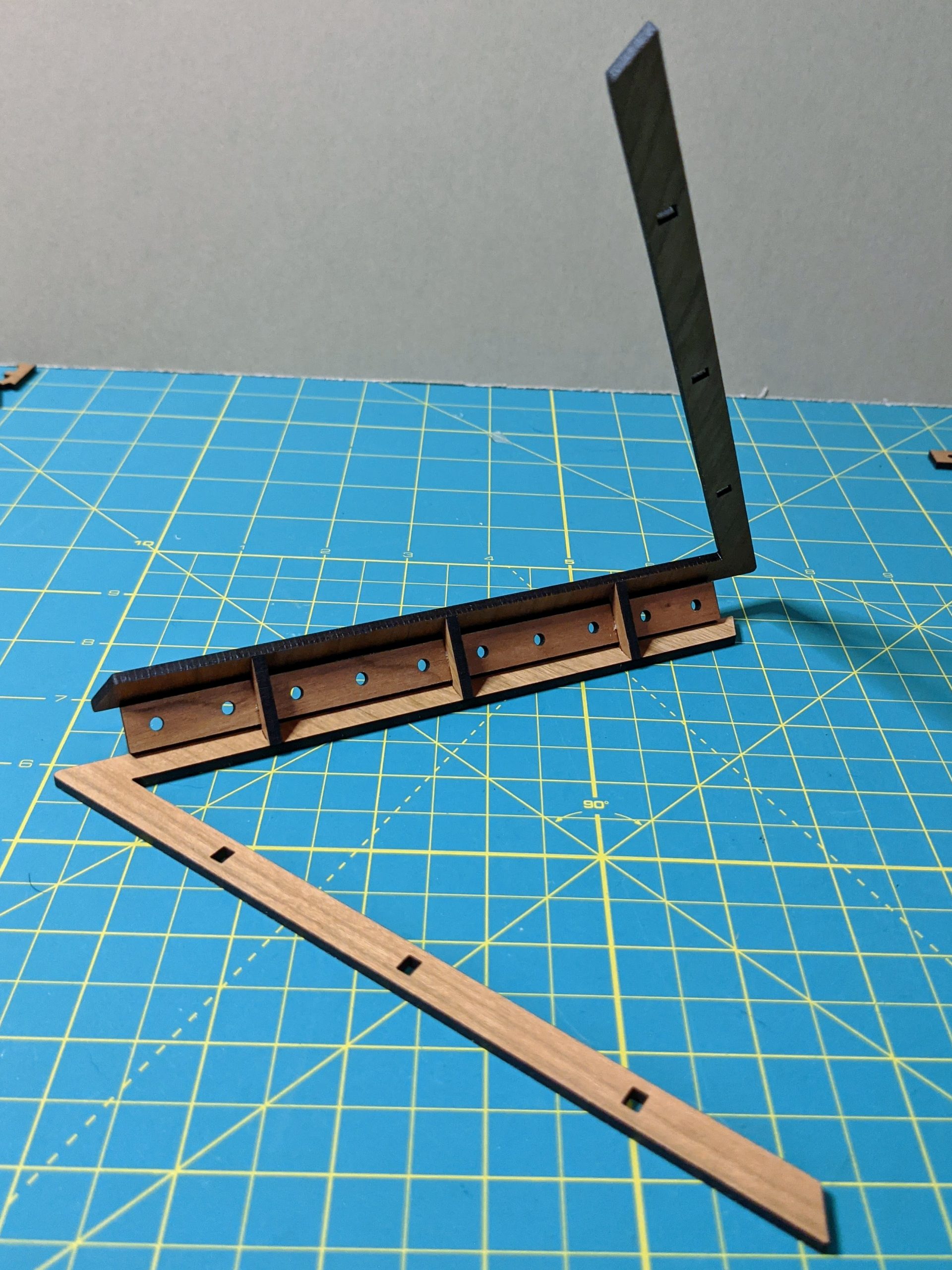
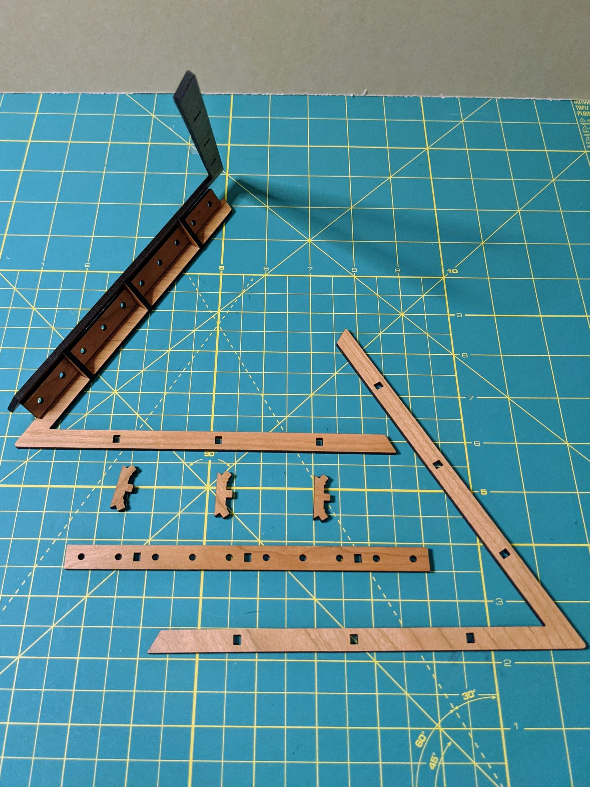
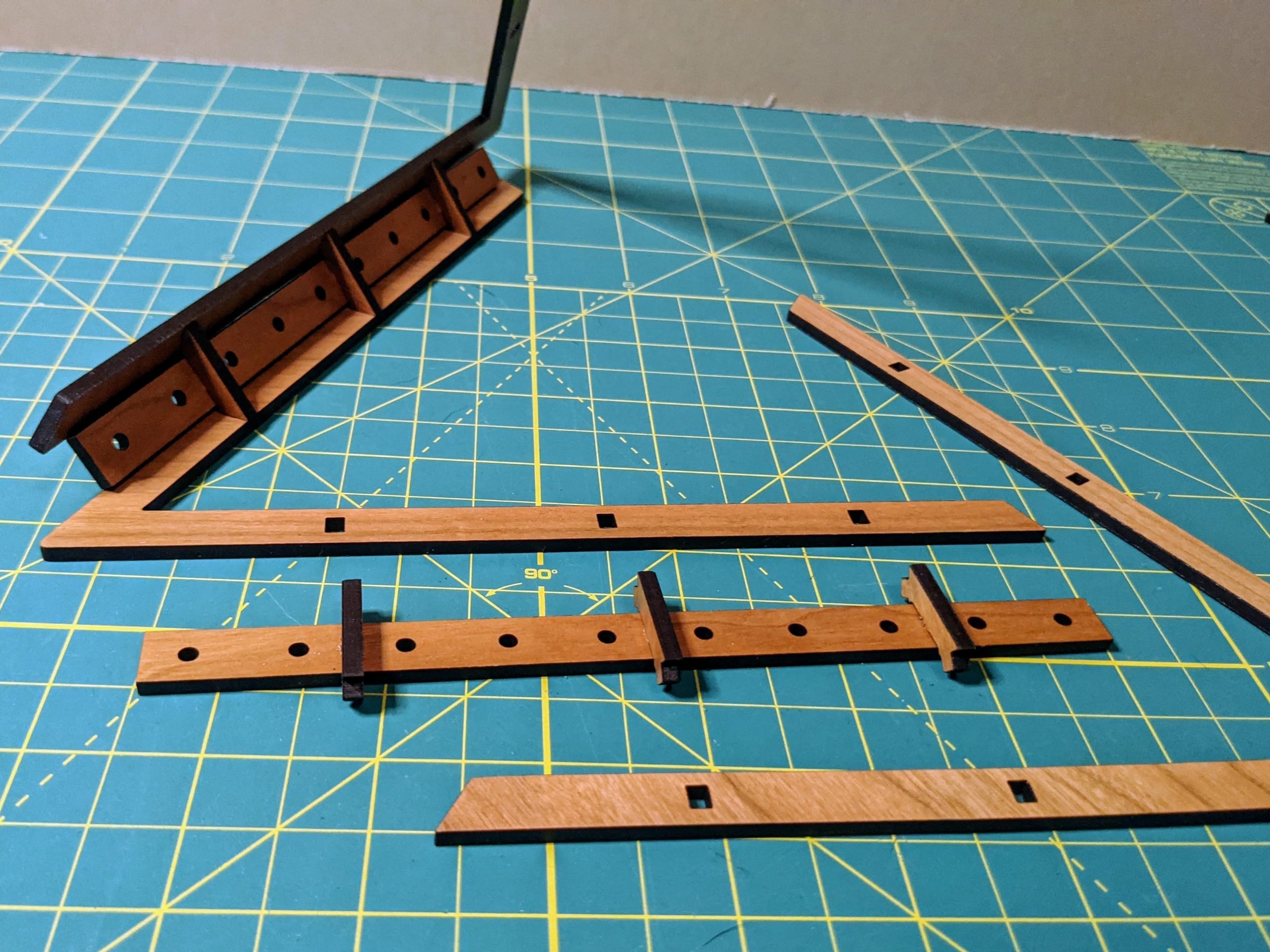
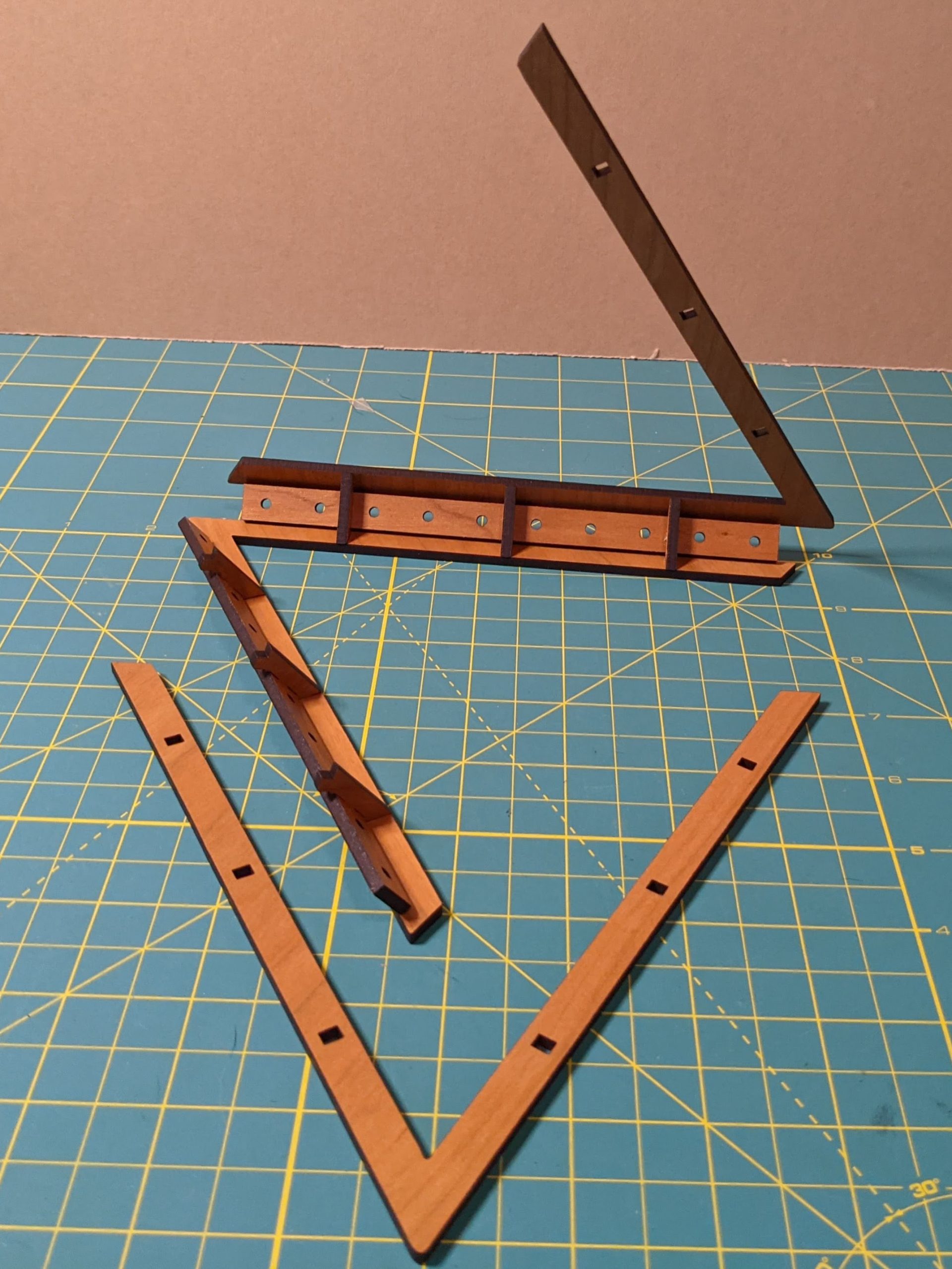
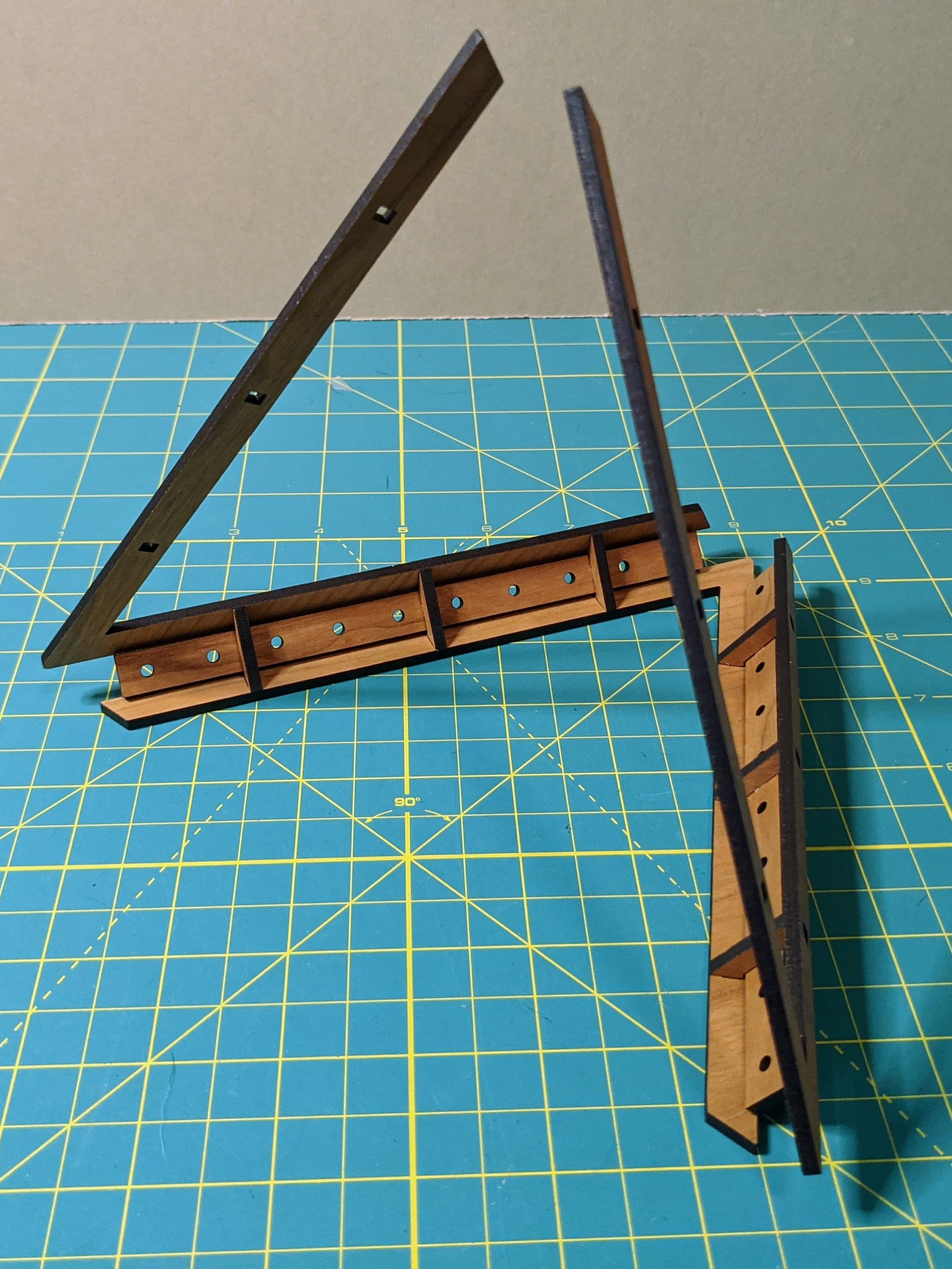
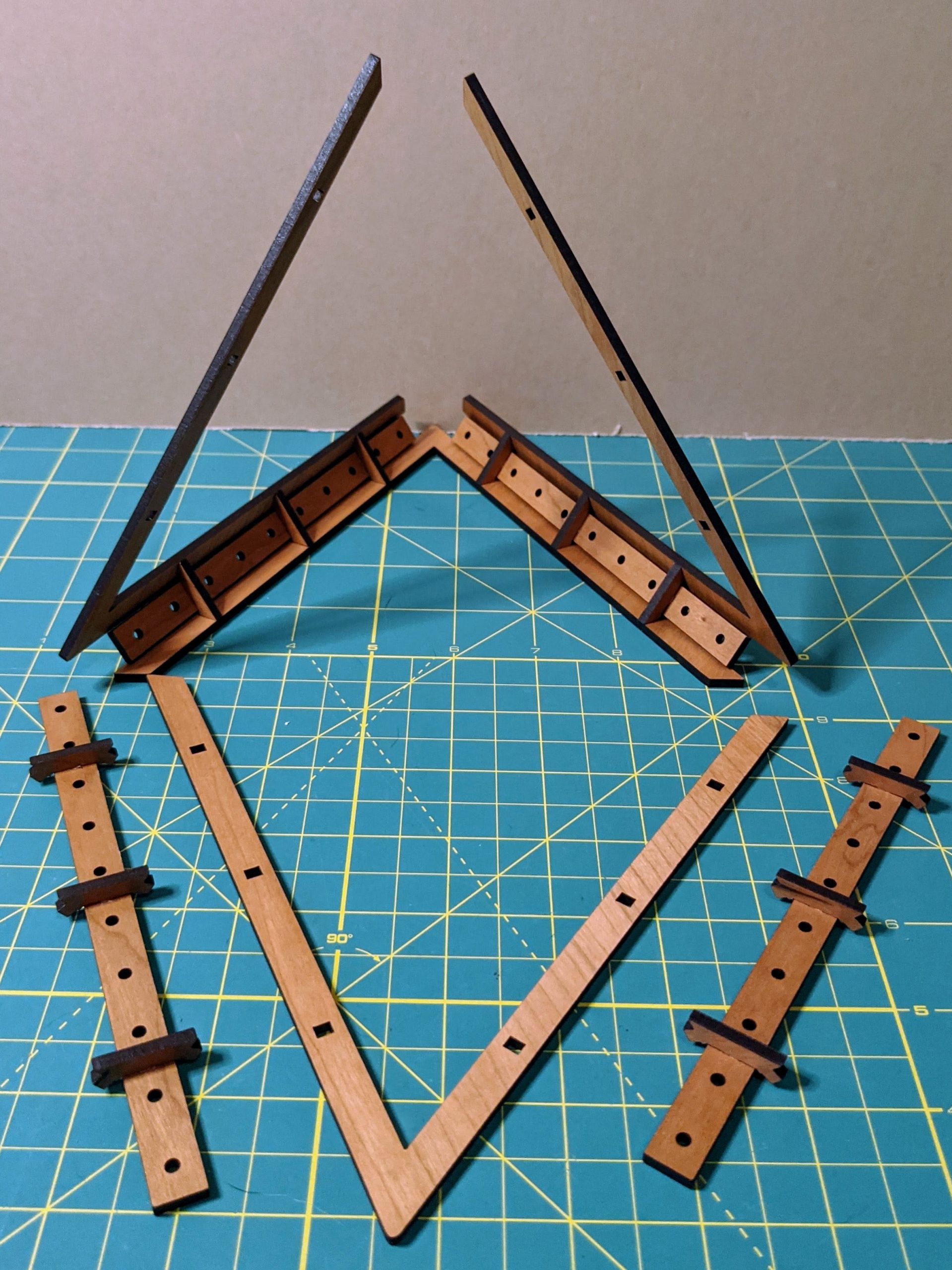
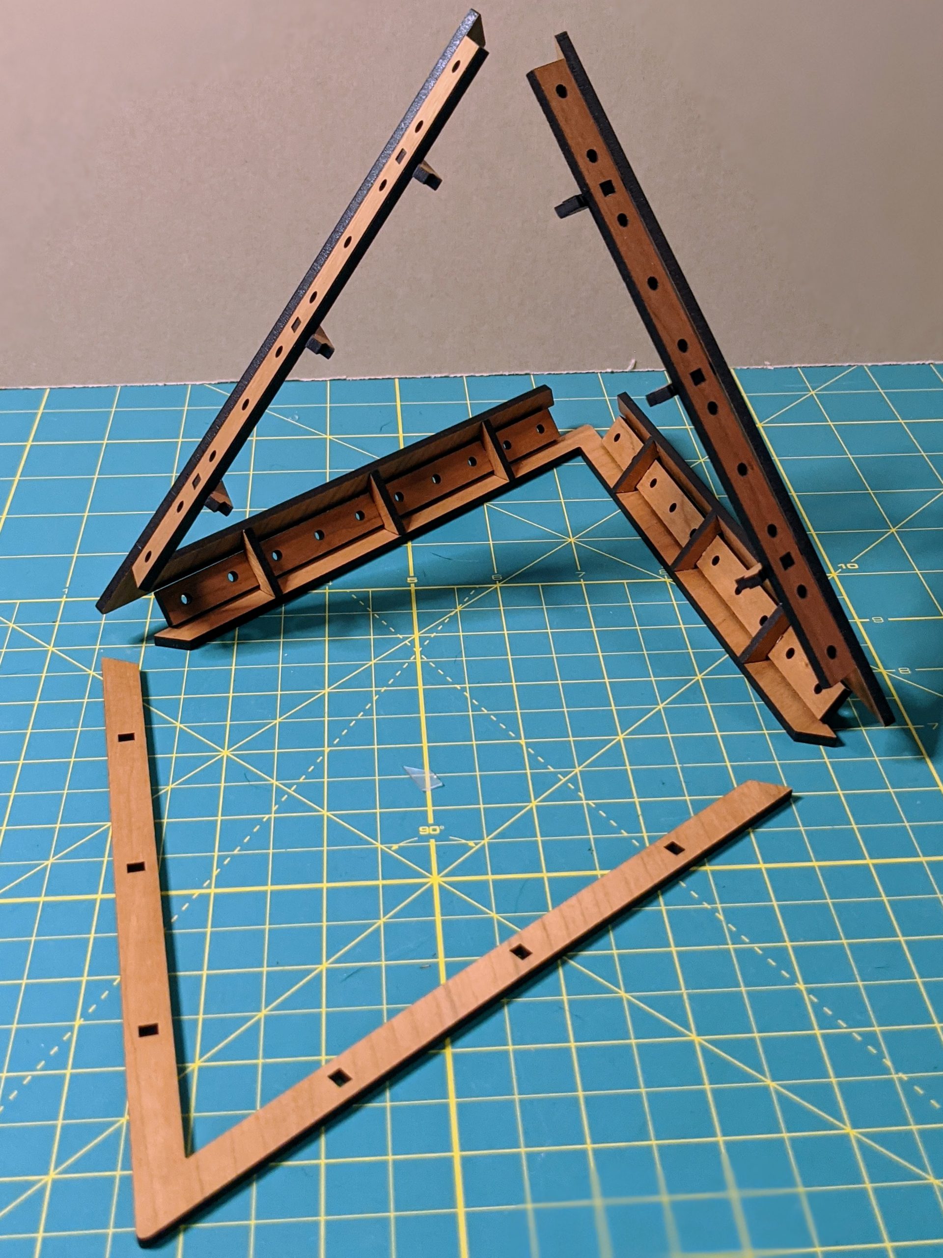
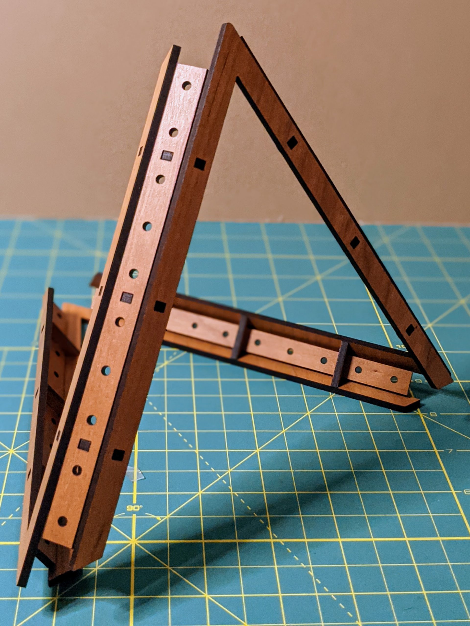
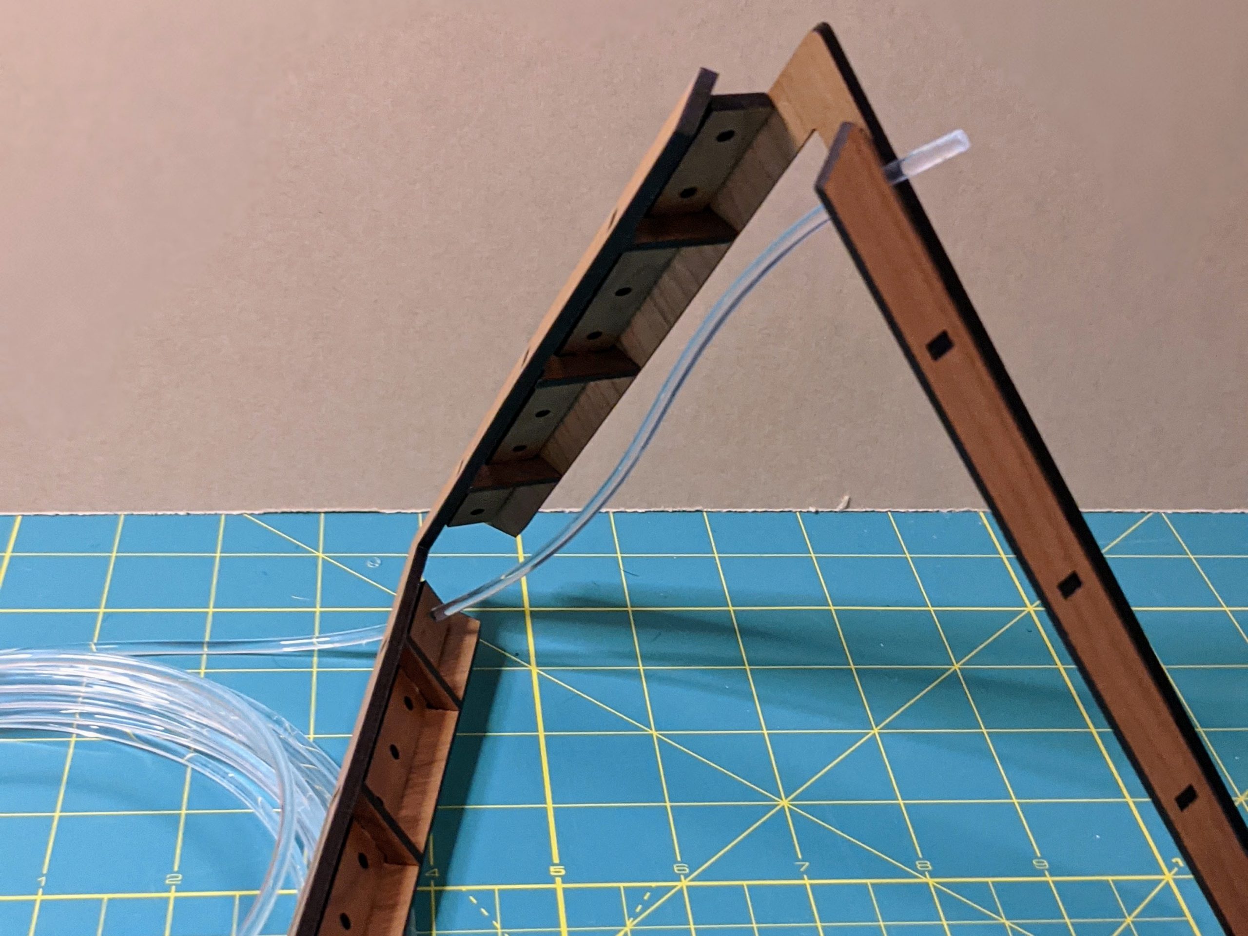
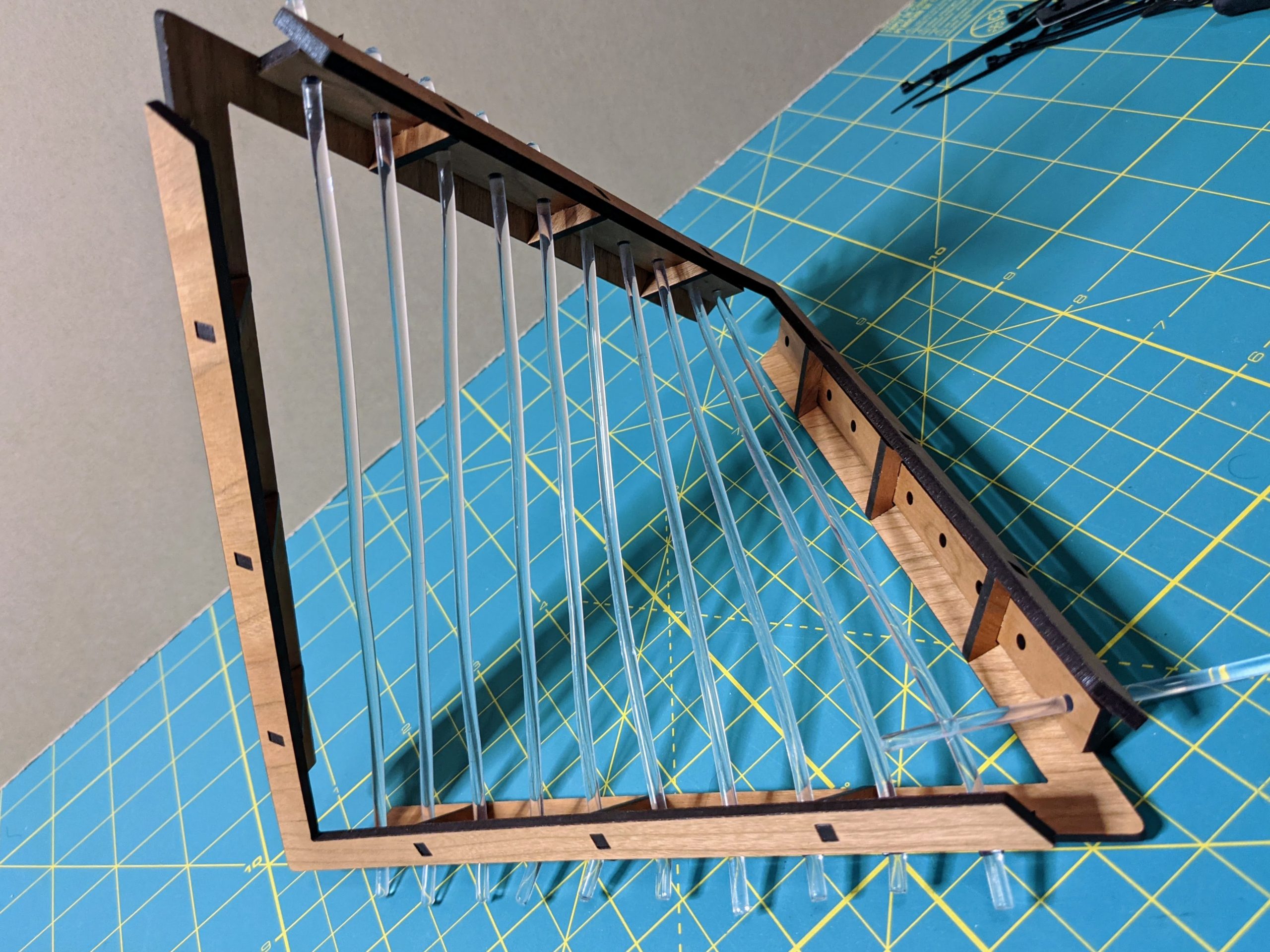
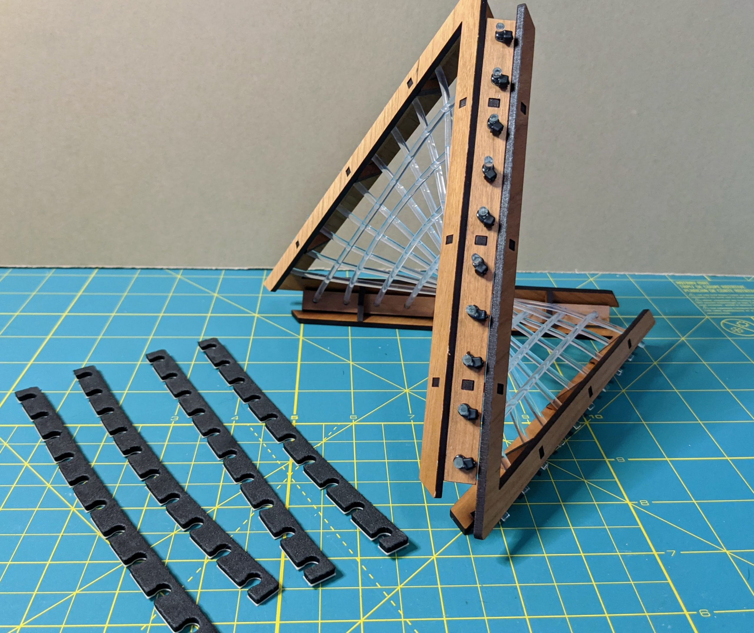
Assemble the Wood Frame
Laser cut the frame pieces from the wood sheet, and assemble them into a 3D V-shaped frame using the connector pieces. The images below show the steps to follow to build the frame. I was able to press-fit the pieces well enough to hold the frame together quite sturdily, but you might want to place a bit of wood glue on the tabs and slots before joining them in order to hold the assembly together.
String the Fiber Optic Cable
For this step, we’ll be stringing the fiber optic cable through holes in opposite sides of the frame. The holes in the frame are just slightly larger than the 3mm cable, so the fit will be snug, but you should be able to string the cable through without too much difficulty. If you have problems getting the end of the cable through the hole, it will help to cut the end of the cable at a slight angle before threading it through.
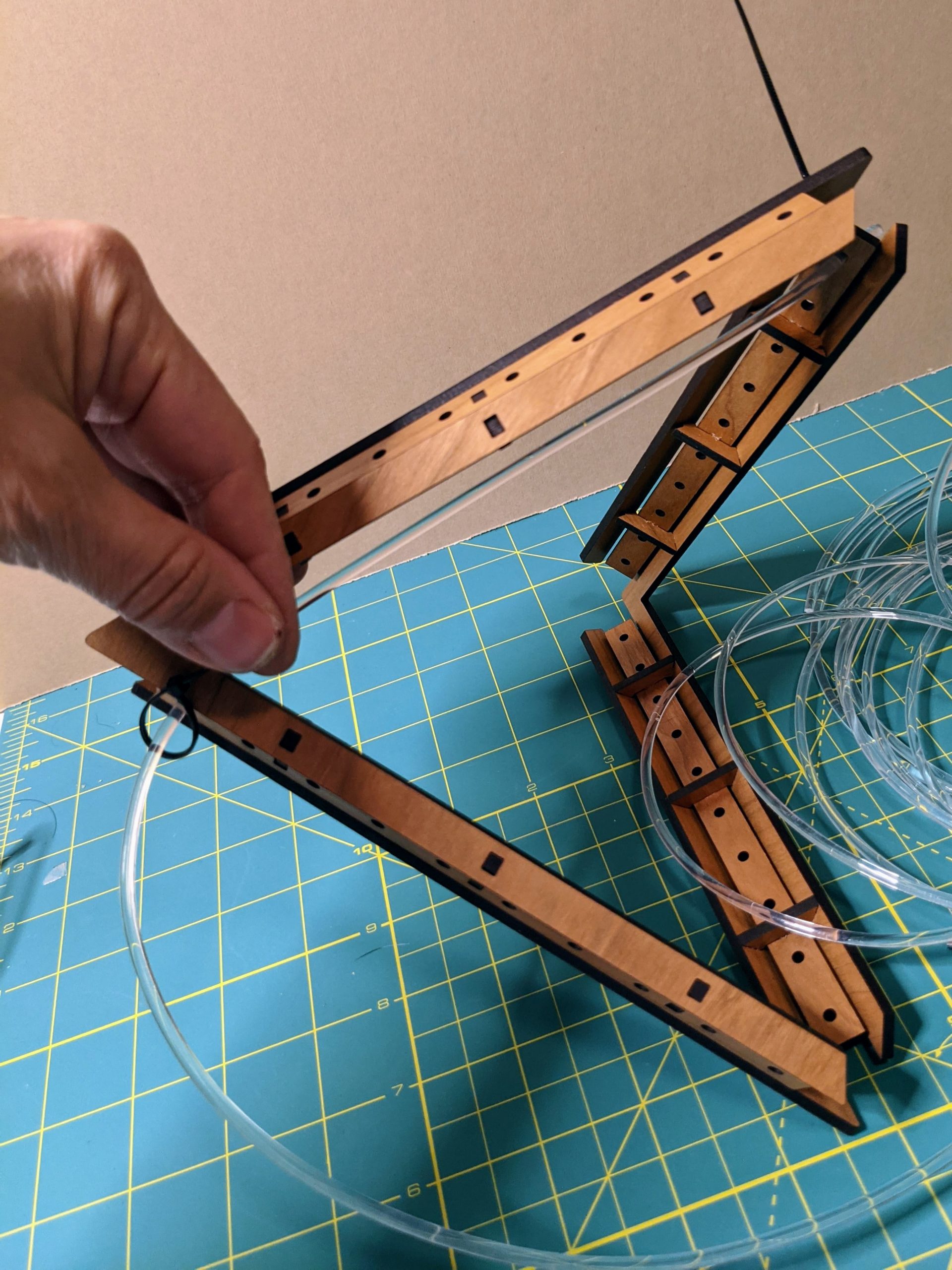
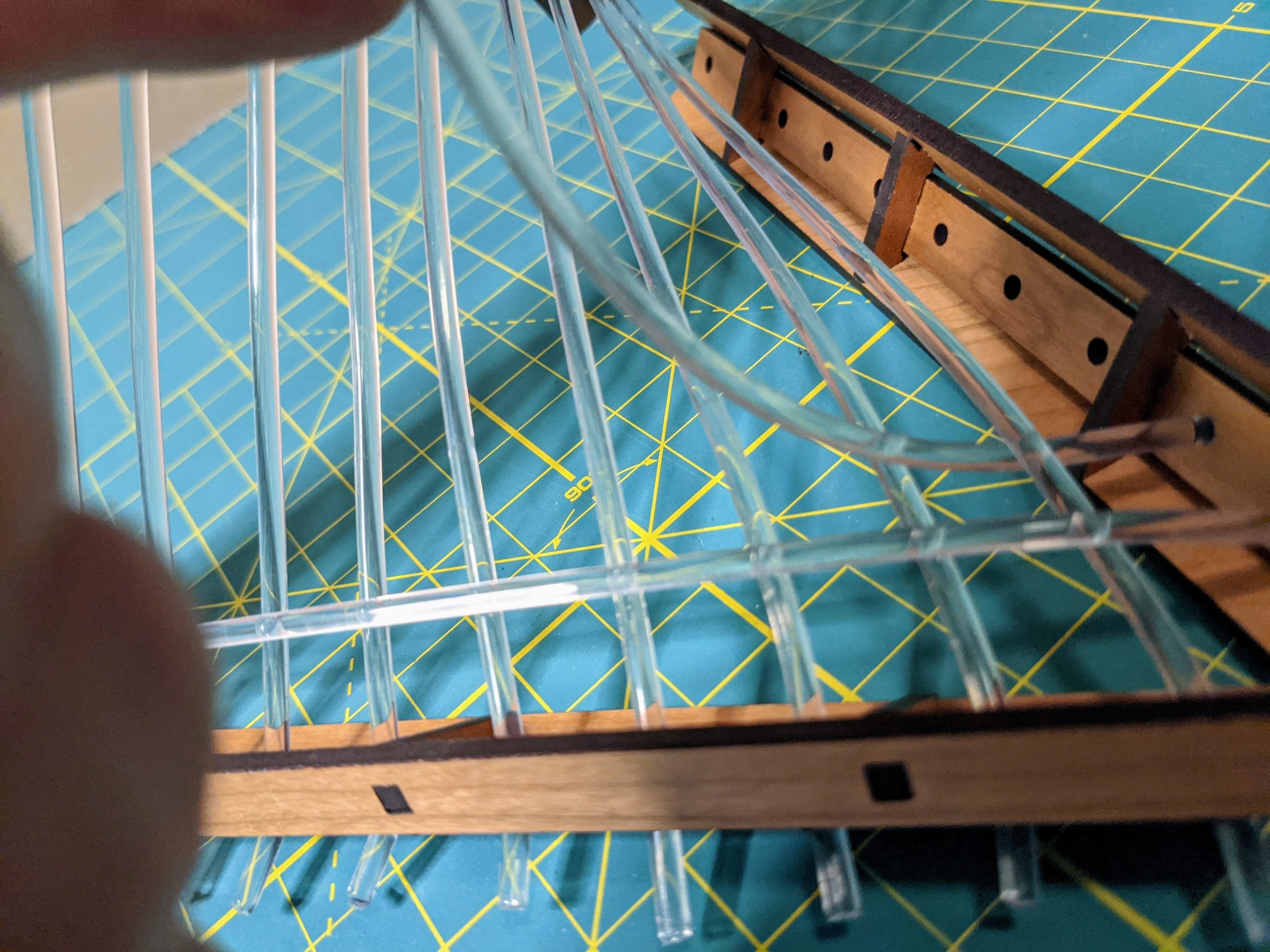
Once you are ready to string the second set of cables which cross the first, you’ll want to decide how best to align them with the first set of cables. The fiber optics aren’t flexible enough to weave them in and out of each other, but I found that it looks nice if each cable in the second set crosses over the first set at a different place.
In the pictures below, you can see that the first cable in the second set passes on top of all 10 of the first set of cables. The second cable in the second set passes under the first cable in the first set, then over the 9 remaining cables in the first set. The third cable in the second set will pas under the first two cables in the first set, then over the remaining 8 cables, etc…
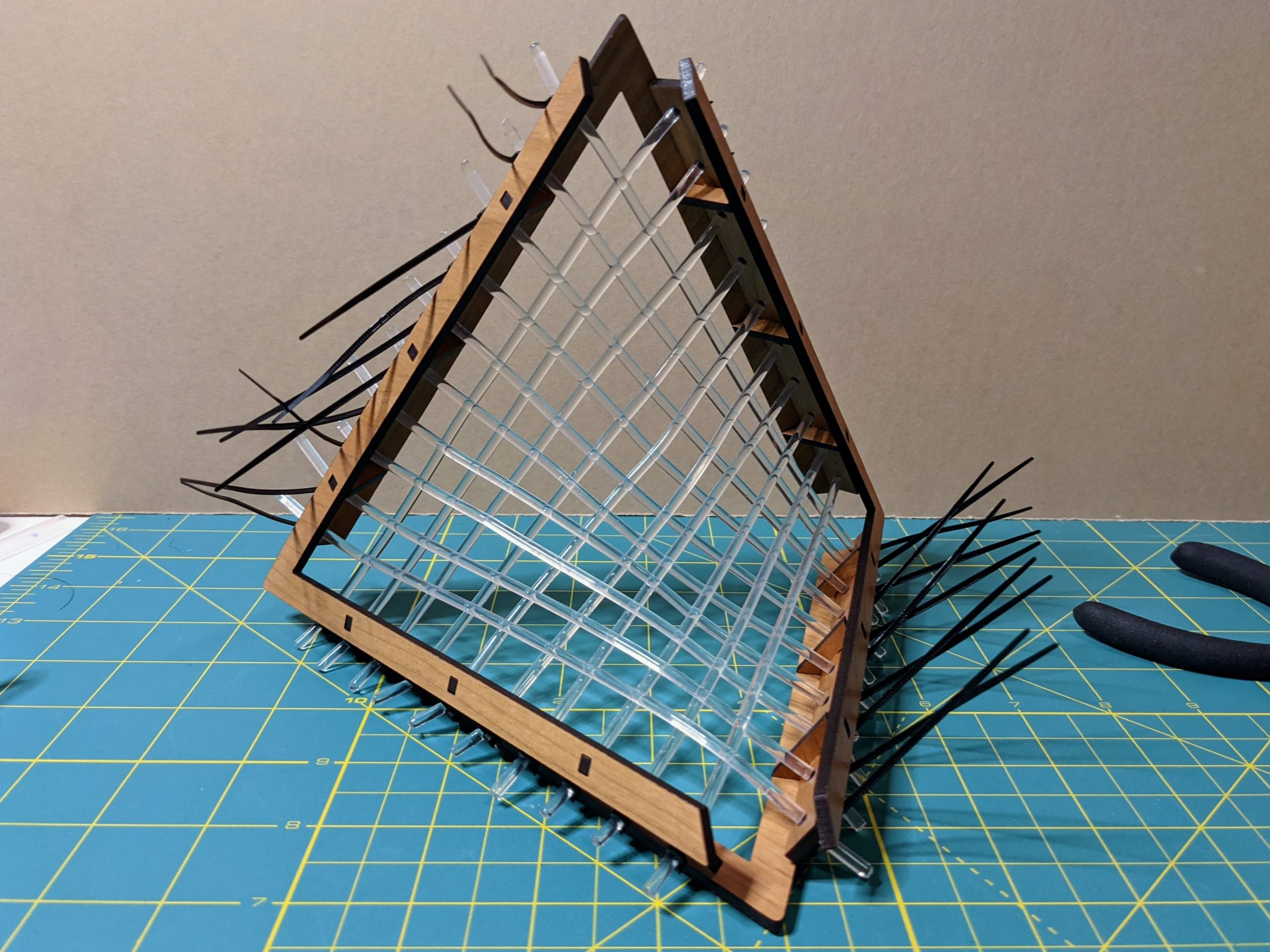
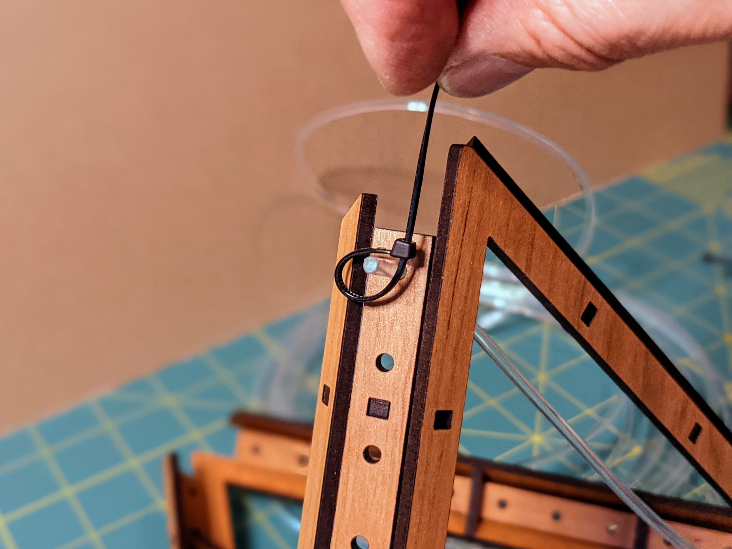
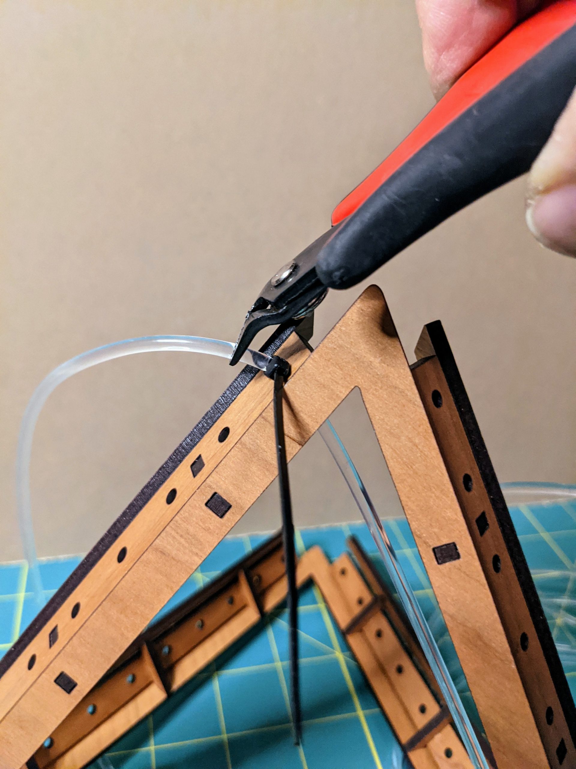
Trim the Zip Ties and Fiber Optics
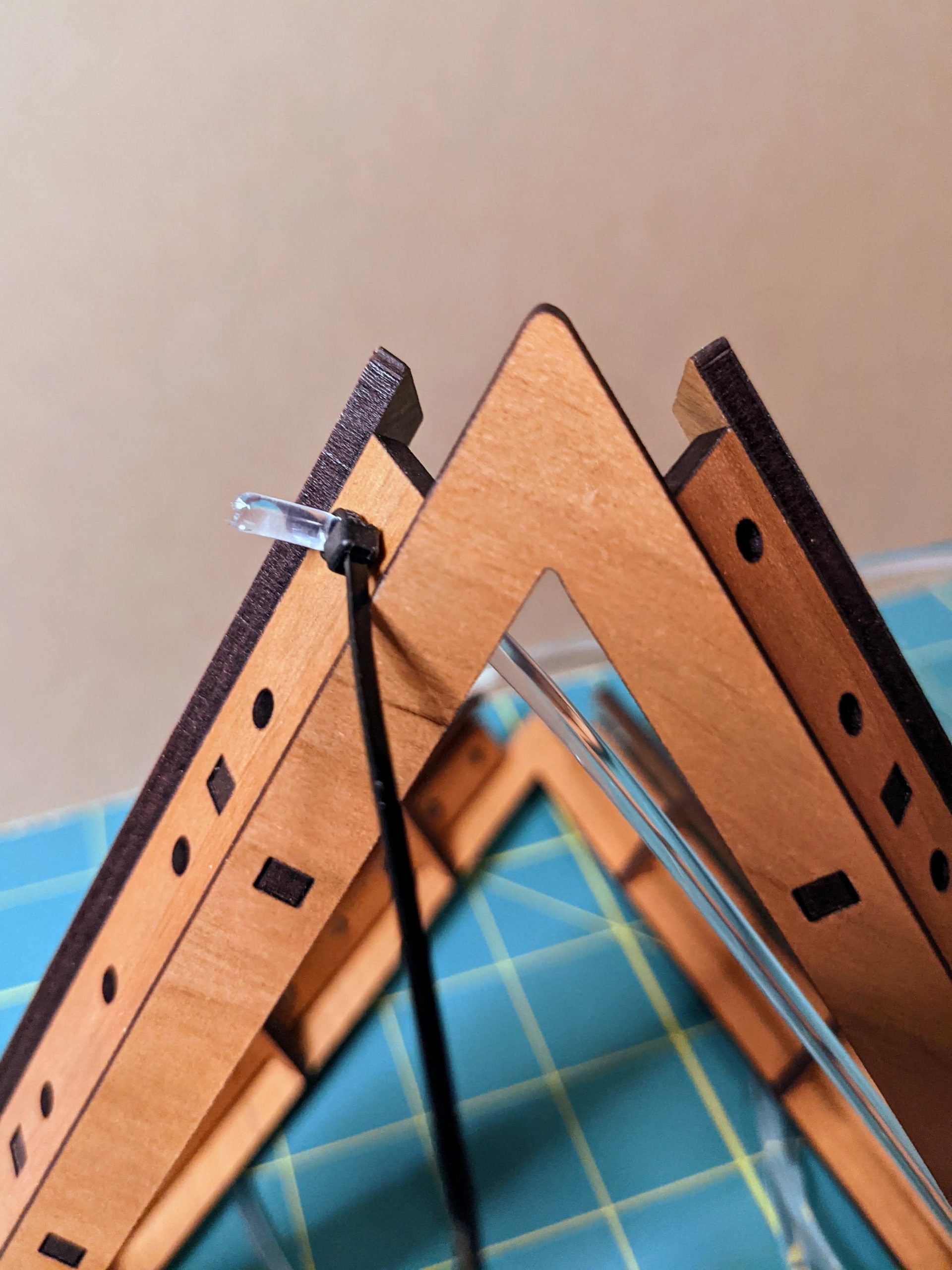
Once the frame has been strung, double check that all the zip ties are snug and secure the cable well. Also be sure that the zip-tie connectors on each side of the frame point in the same direction, perpendicular to the frame edge. Then, using snips, cut off the ends of all the zip ties close to the clasp.
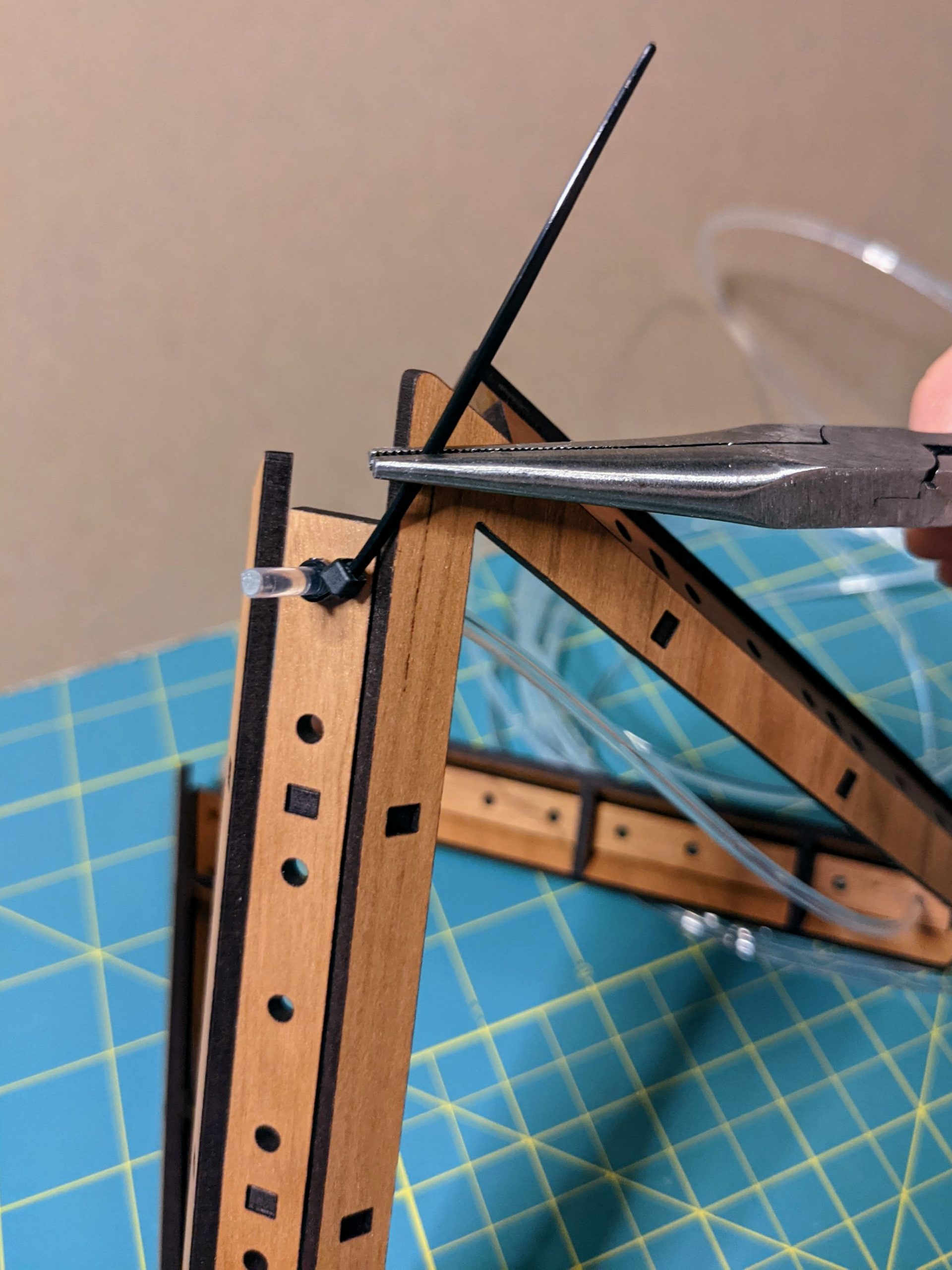
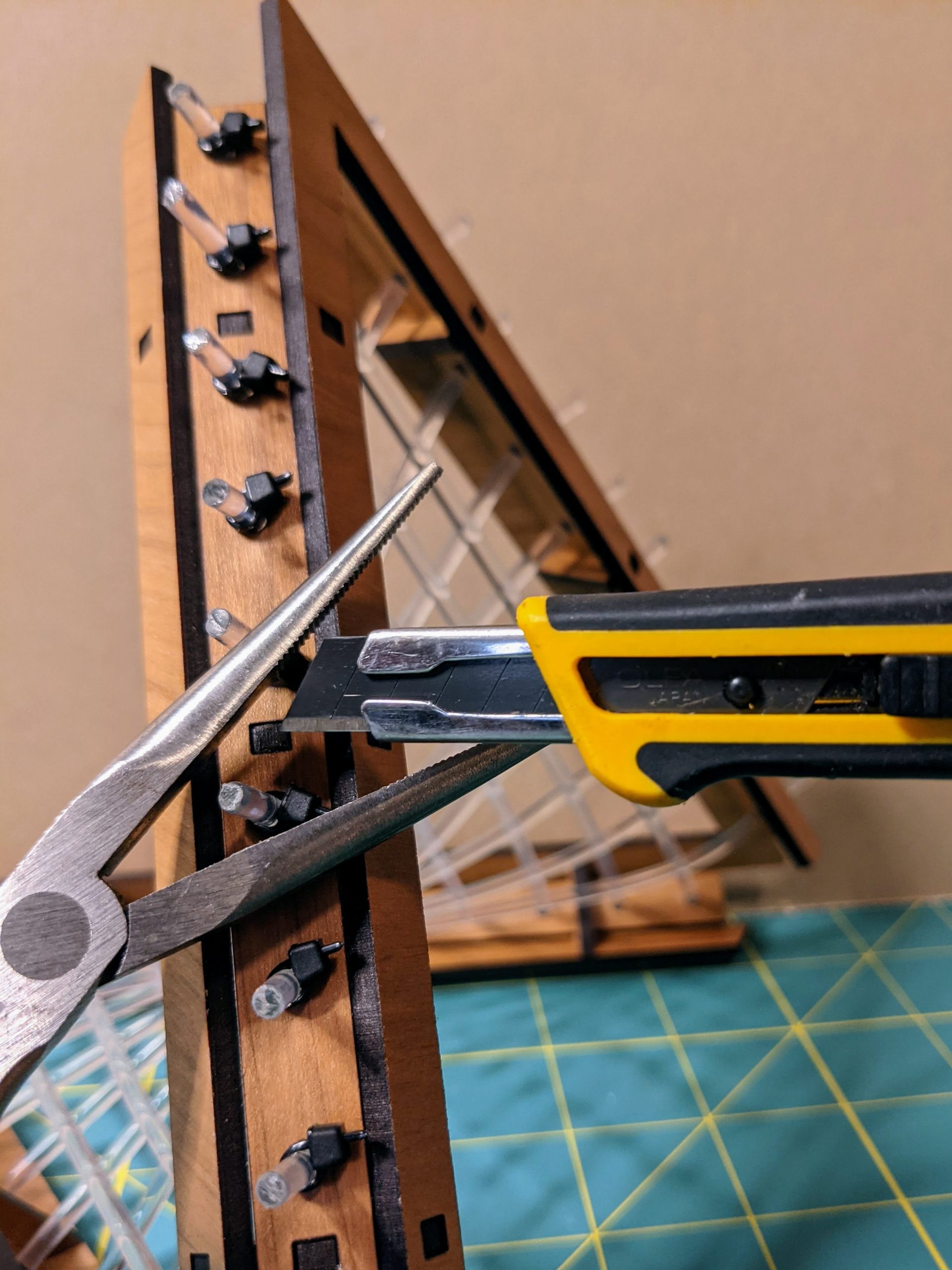
Once the zip ties are trimmed, go around to each cable end and, using a sharp craft knife, trim the end of the fiber optic cable about 3mm past the end of the zip tie. You’ll want to use a sharp knife to make a clean cut so that the maximum amount of light can enter the cable at the end. Try to make the cut surface perpendicular to the fiber optic cable.
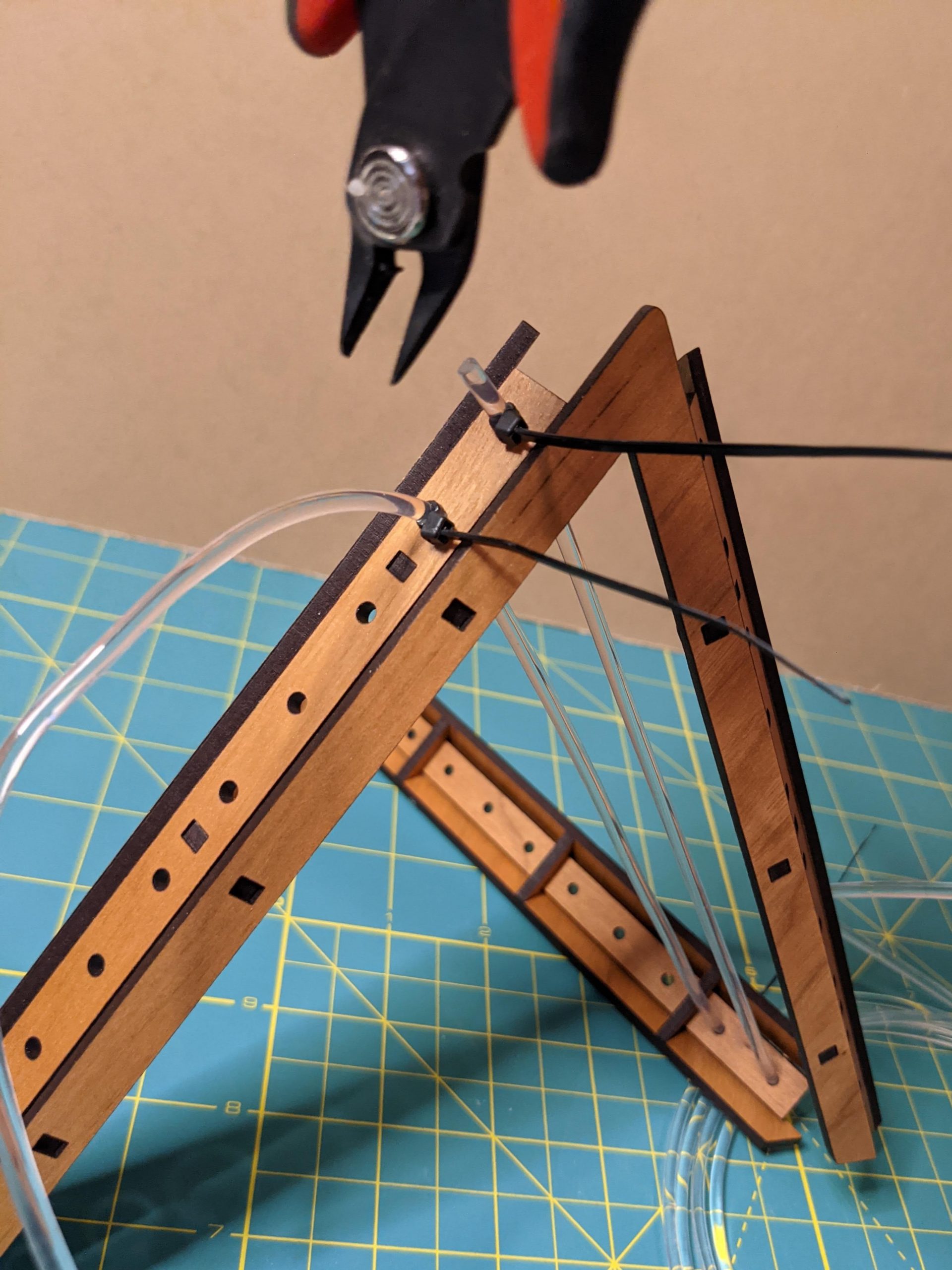
It’s a bit awkward to cut the cables directly on the frame. The trick I used is shown below. I used an open pliers as a surface just below the end of the fiber optic cable. It was then easier to slice through the fiber optic cable with the mouth of the pliers pushing up on the end of the fiber optic strand for resistance.
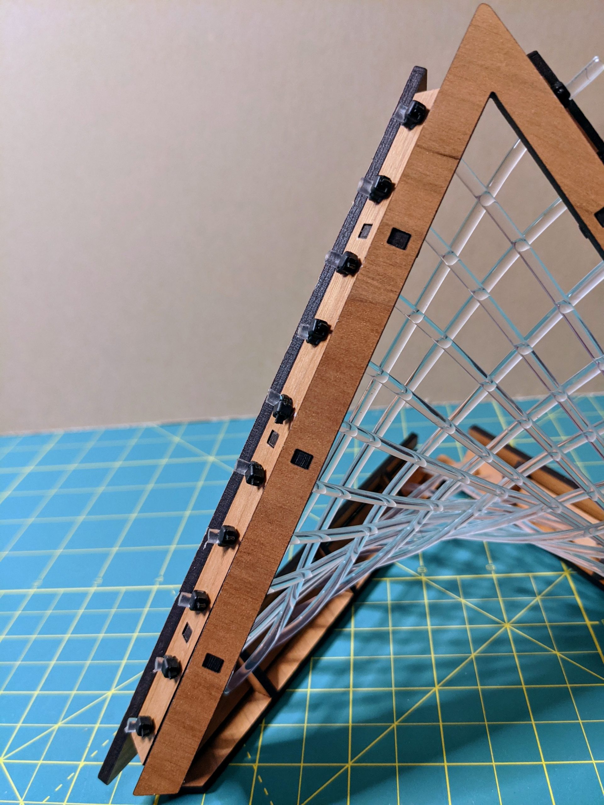
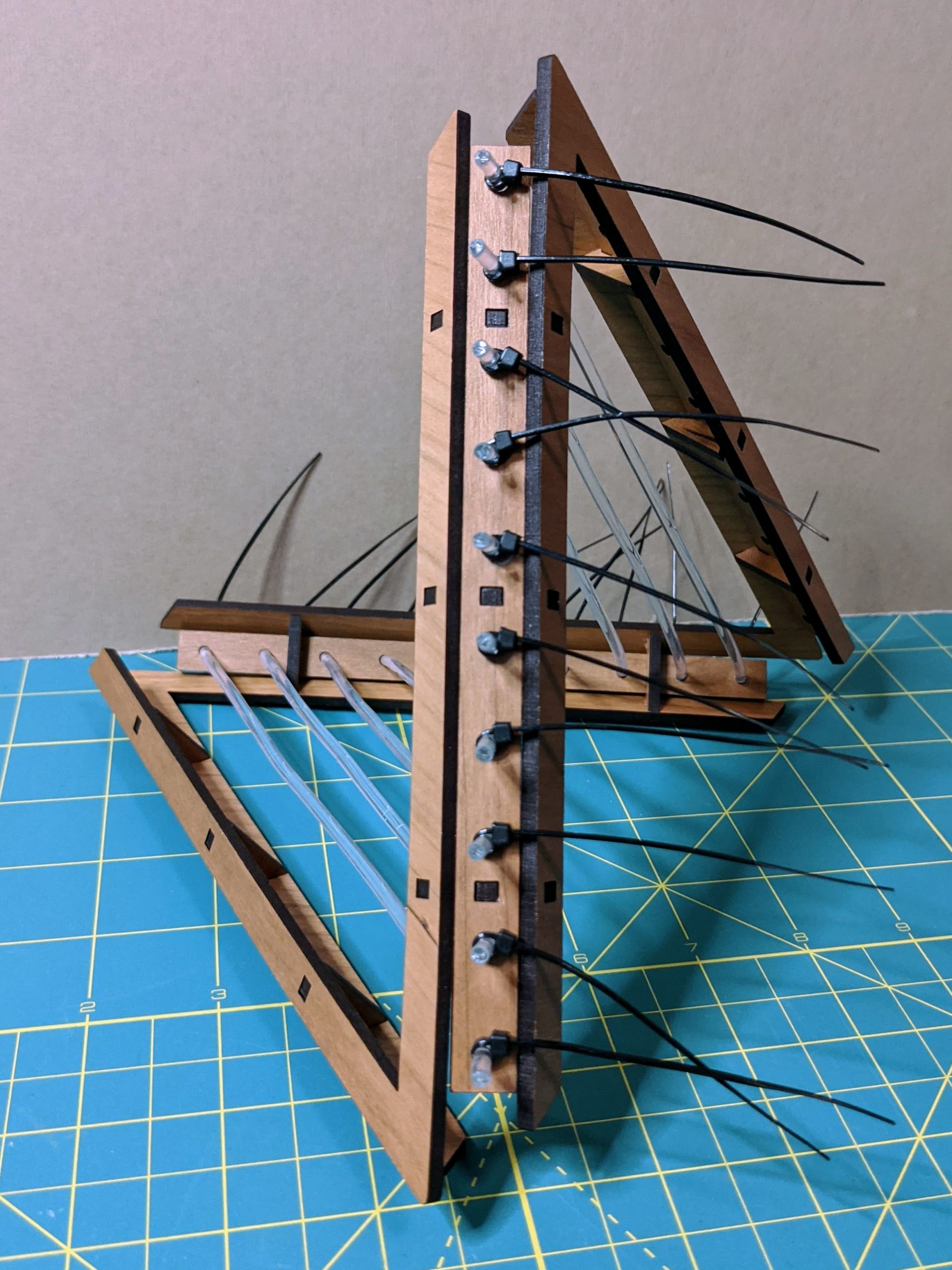
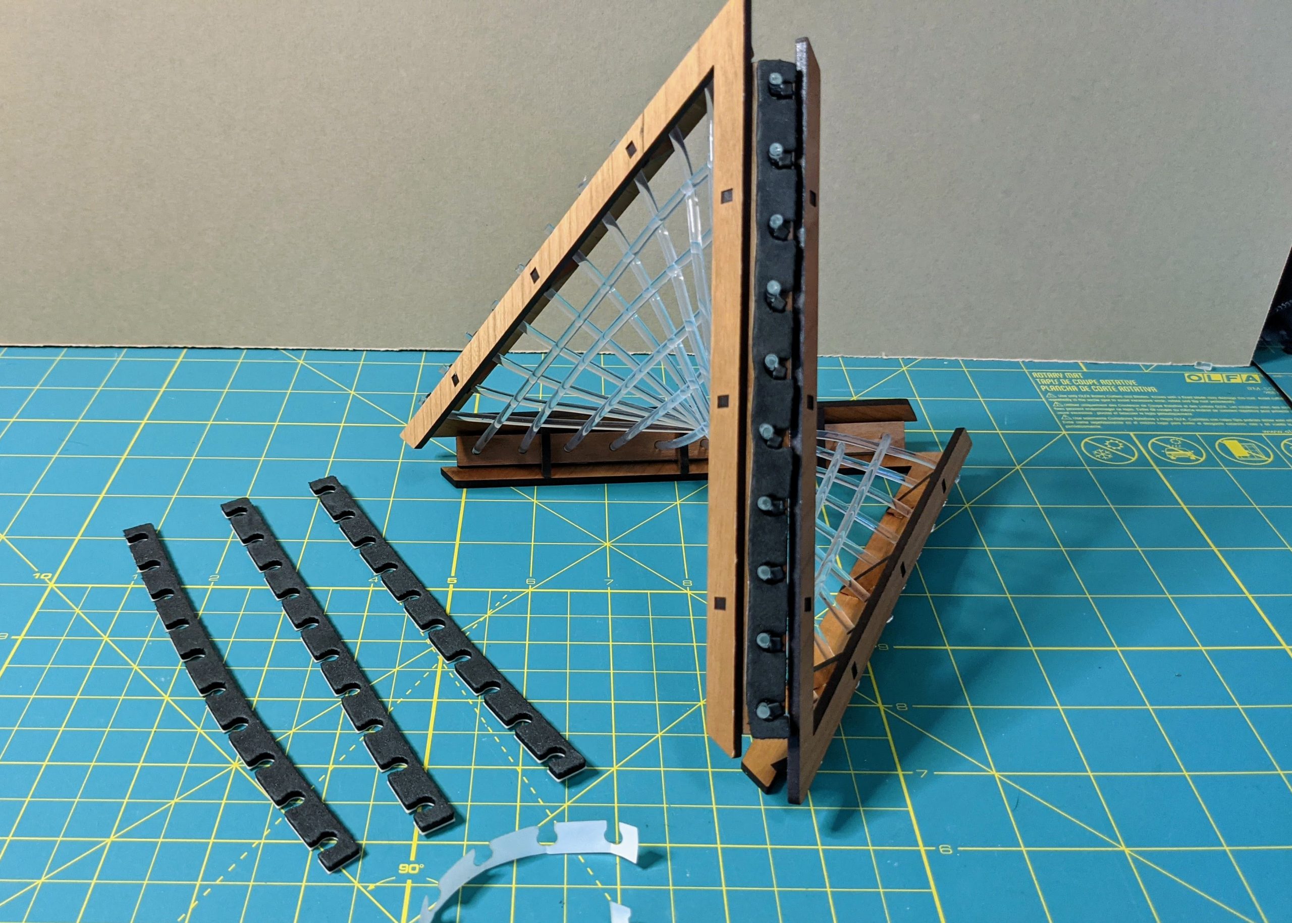
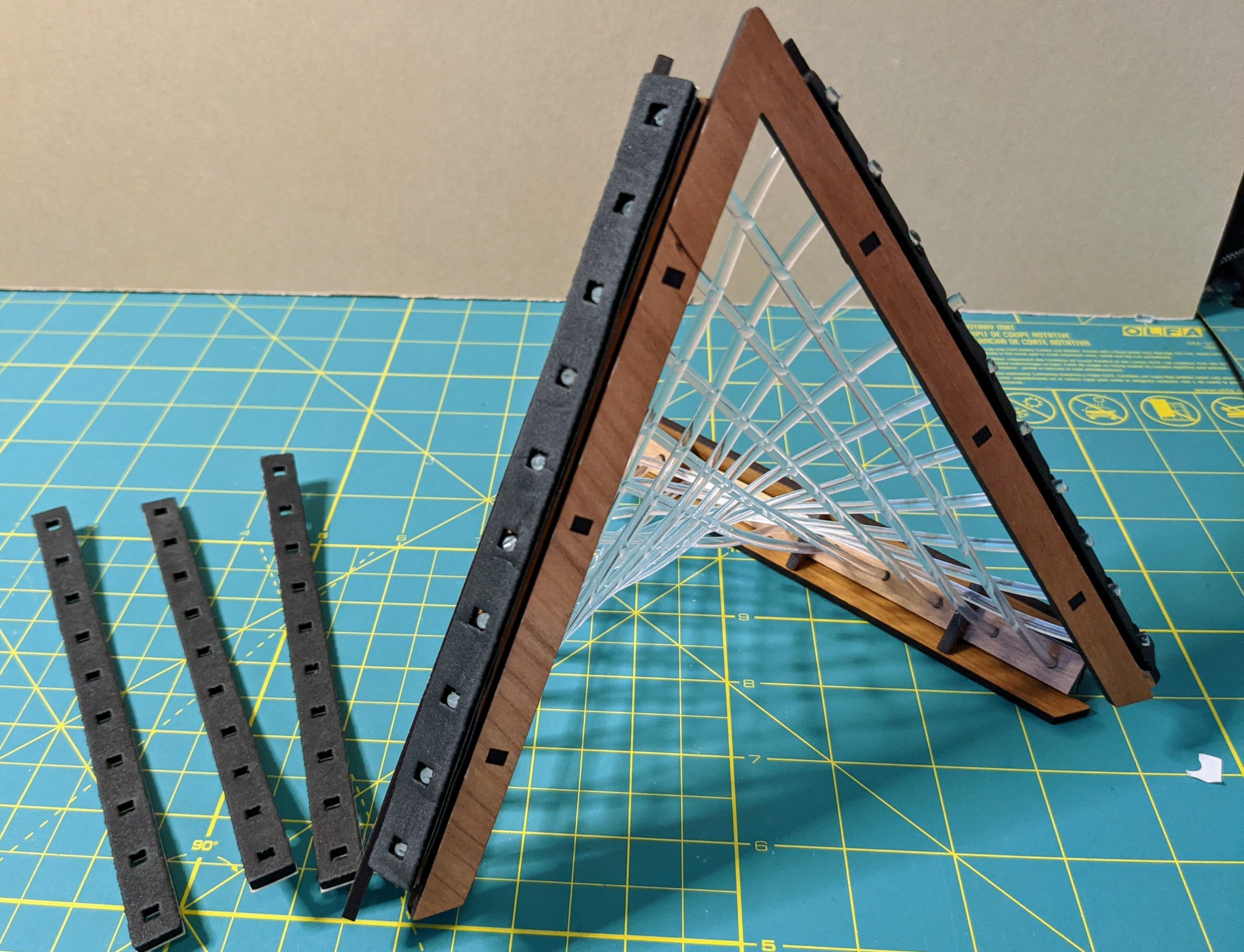
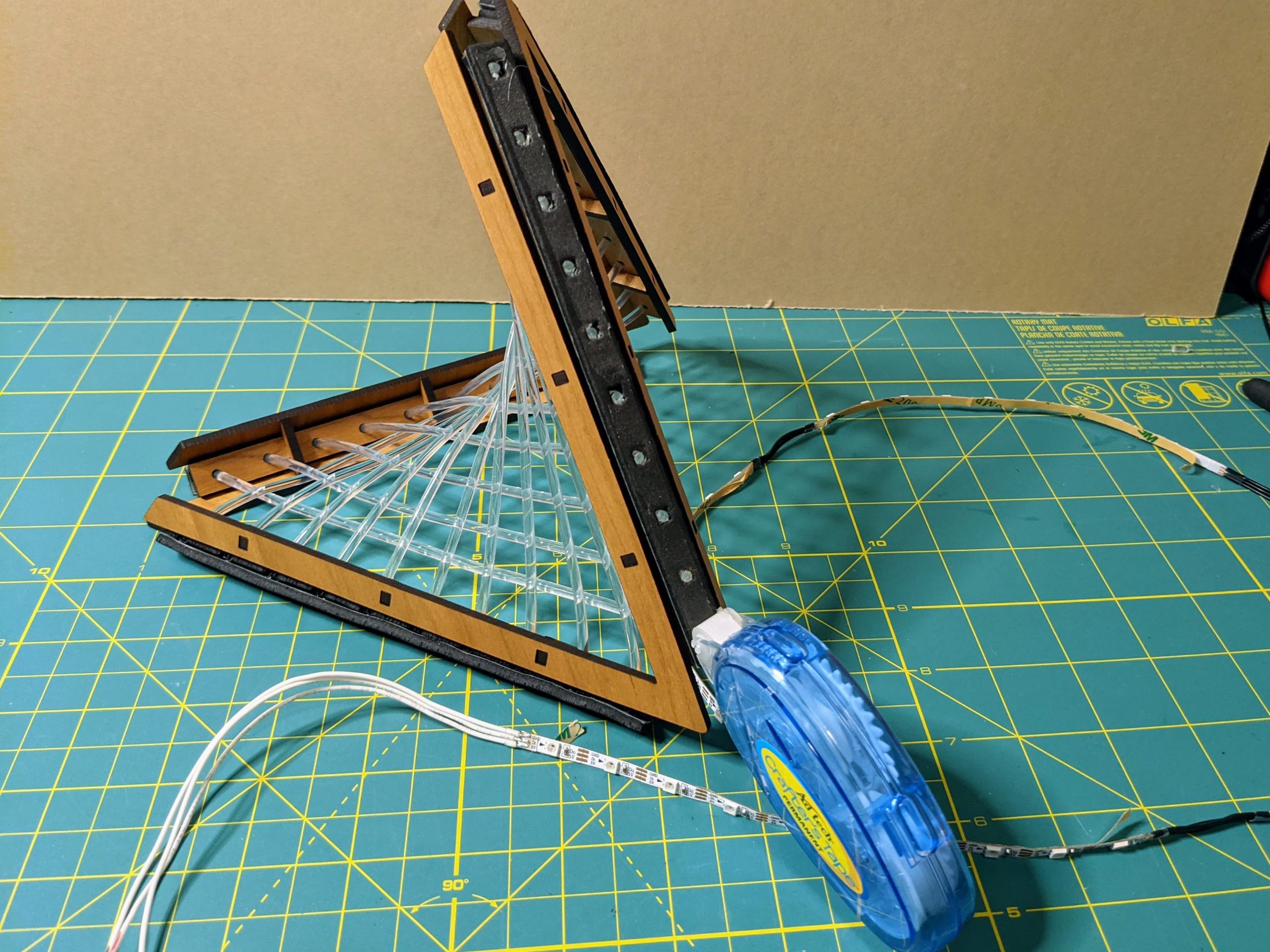
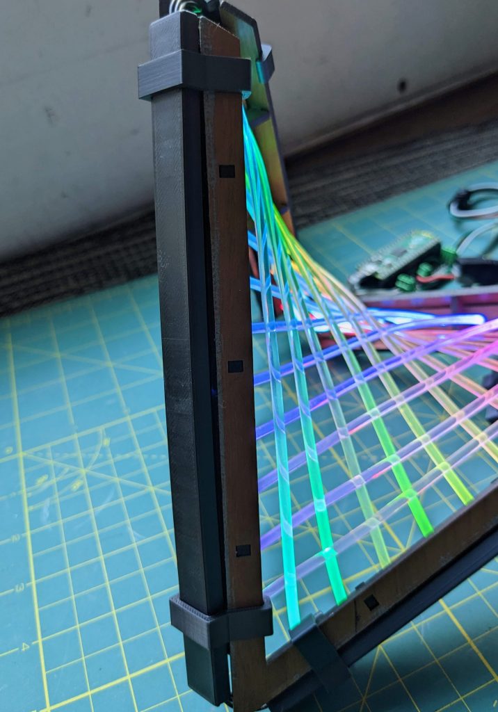
Attach the Adhesive EVA Foam
We’ll layer two of the cut EVA foam strips over each edge. These will help to position the LED strips so that the LEDs can shine directly into the ends of the fiber optic cables. Following the steps laid out in the images below, you’ll first attach the strips with the notched edges so that each zip-tie connector sits in a notch. Next the EVA foam strips with the square cutouts get stuck over the first foam strips so that the fiber optic cables are centered within the squares.
Solder and Attach the LED Strip
After two foam strips have been layered on top of each frame edge, you’ll need to prepare the LED strip. Use an LED strip where the LED spacing is 60 LEDs/m. The square cutouts on the top layer of the EVA foam are just large enough to hold 3535 (mini) sized WS2812Bs. If your strip has the larger (5050) LEDs, you’ll probably need to enlarge the square cutouts to hold them.
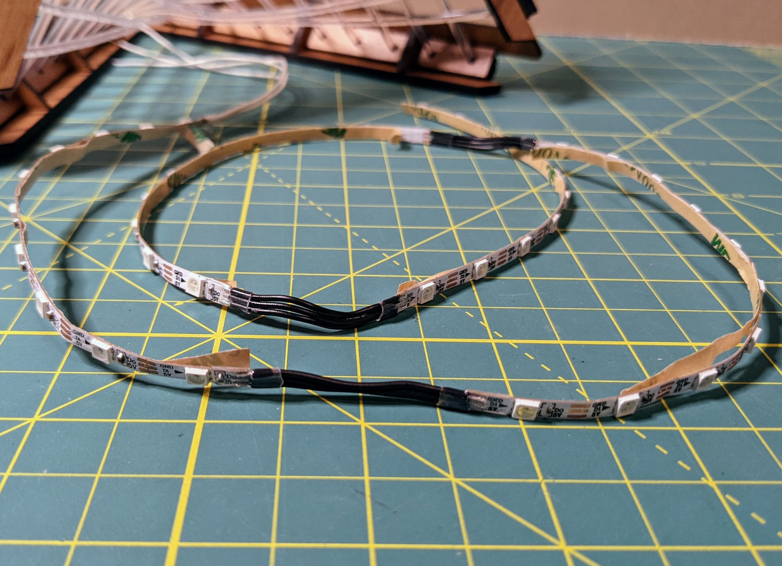
Cut four lengths of 10 pixels each from your LED strip. Try to avoid having a join in the middle of your strip unless it doesn’t affect the LED spacing. Solder Signal/Power/Ground wires to the input of one of the strips, then solder all the strips together in sequence. The wires connecting each strip segment should be about 1.25″ to 1.5″ in length. Reinforce solder joints with shrink tube for sturdiness. Test the LED strip to make sure the connections are good.
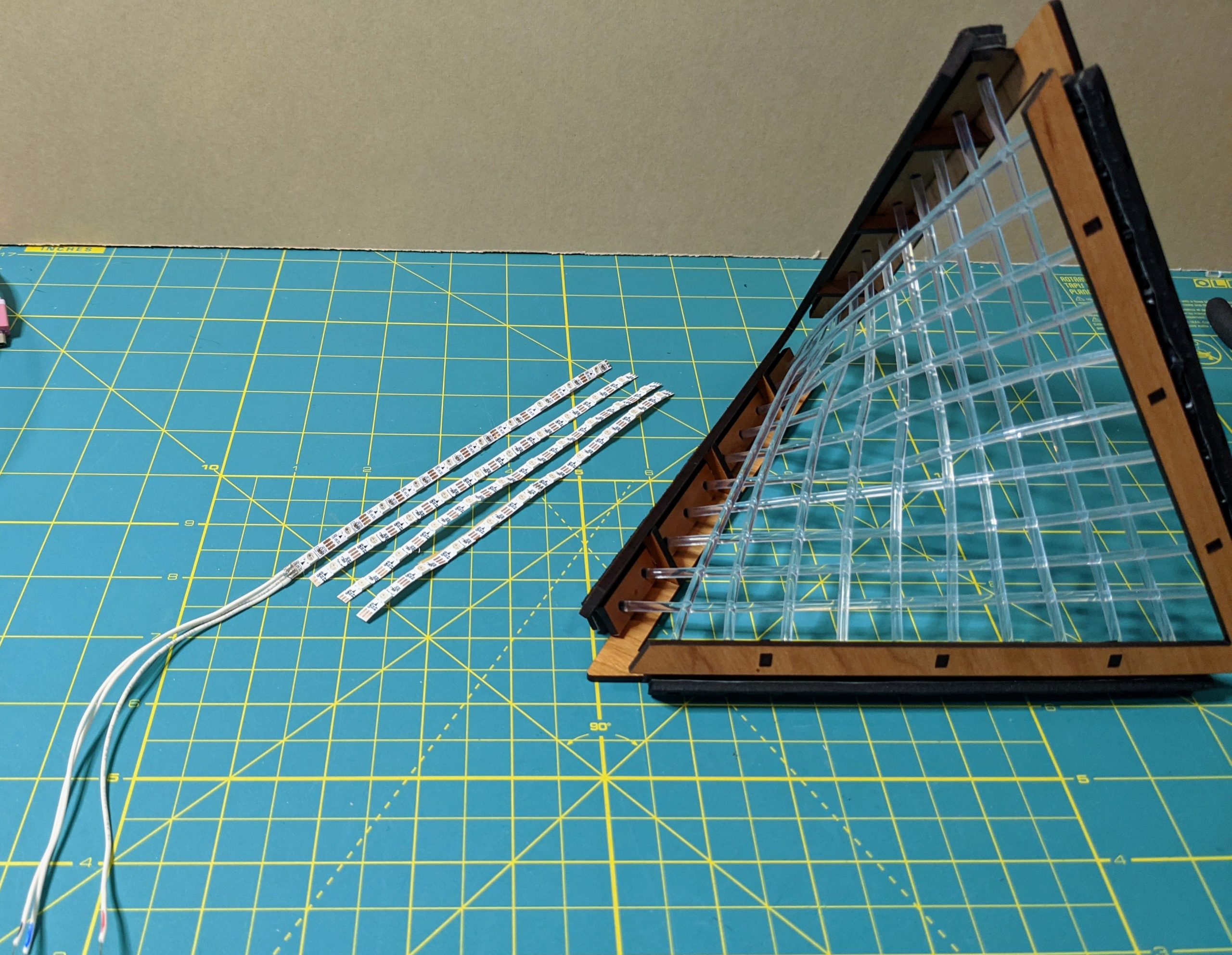
Now we’ll attach each segment of the LED strip assembly to a side of the frame. If you have crafters’, or similar tape, it will help to keep the strips in position if you run a length of the tape down the middle of the foam piece before sticking the LED strip face down on top of the foam. When you place the LED strips, be sure that each LED sits directly in the middle of one of the square cutouts.
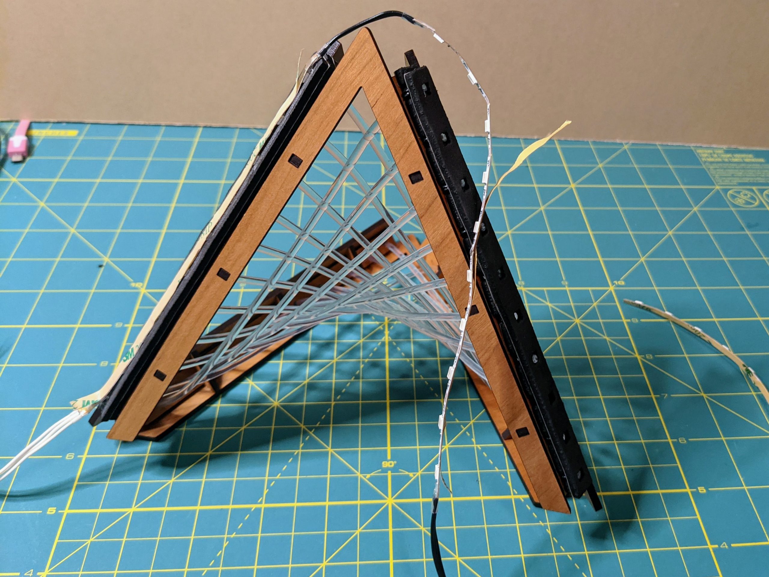
Cover the Edges
Update (12/25/22) – I recently pulled this build out of storage, and the duct tape method of holding the strips in place wasn’t surviving too well, so I 3D printed covers for the frame edge and clips to hold them in place. You can print 1 cover and two clips for each edge from the STL files given below the images:
The last step (if you don’t 3D print covers) is to cover the edges of the frame with 1″ wide strips of tape (duct tape works best) to hold the LED strips in place. I tried using a decorative crafters tape for one of the builds pictured below. The crafter’s tape lifted off, so I ended up having to glue it down. You can use whatever covering works for you here.
Get Lit!
Now that you’ve build your fiber-optic hyperbolic paraboloid, you’ll want to code some fun patterns for it. Each fiber optic cable has LEDs on both ends, allowing for some fun color-mixing effects. I’ll put the basic CircuitPython code I wrote for the demo on the GitHub repository for this project: https://github.com/geekmomprojects/fiber-optic-hyperbolic-paraboloid. Enjoy!

One thought on “Fiber Optic Hyperbolic Paraboloid”